Two different types of rectilinear combing machines are currently used in the short-staple spinning mill:
Single-sided machines with 8 combing heads; and
Double-sided machine with 12 combing heads.
To
give the equivalent production rate, the single sided machine is forced
to operate at a higher nip rate. On the other hand, the one-sided
machine has the advantages of being rather less complicated and of
enabling 8 doublings, while being rather easier to automate.
Description of Functions of the Comber
Fig. 1 – Cross-section through the comber
The material is fed in the form of lap Fig. 1, 2)
which rests on two support rolls (3), on which it slowly unrolls also.
In figure Lap (1) represents reserved lap for next cycle...
On
its way into the nippers the web passes over an eccentric shaft (4)
acting as a diverter. This serves to keep web tension constant during
the forward and return movements of the nippers.
Forward
movement of the web into the nippers is performed by feed roller (5)
and is carried out in very small steps (around 5 mm).
When feed has been completed, the nippers (Fig. 2) are closed by allowing spring (8) to press nipper plate (7) against the cushion plate.
During
the return swing of the nippers, caused by the oscillation of nipper
shaft (13), the nipped web is presented to combing segment (10) mounted
on rotating cylinder (11) and is combed out.
The
nippers swing forward again to enable the tuft to be detached from the
fiber fringe by rotating detaching rollers (14), which are mounted as a
stationary unit.
Since
the trailing part of the fiber fringe is clamped inside the nippers, no
combing can be carried out in this zone, the rear end of the fiber
fringe has to be combed through another device, it may be needles or
teeth of top comb (9), in order to complete the combing operation. In
order to clean the circular comb, a brush (19) is provided over the
comb.
The
web created by piecing at detaching rollers (14) now passes to a web
plate (15) and then via lead-off rollers (16) to the trumpet (17),
forming the sliver.
Thereafter,
table rollers (18) guide the sliver formed in this way to the
transverse table, on which all eight slivers are combined, drafted and
delivered as single sliver by drafting arrangement.
After the material has been drawn out in this device to a single sliver, it is then coiled in a can.
The following sections provide details of various operations.
The Feed
Feed of the Lap Sheet
Two fluted rollers (Fig.1, 3),
driven at constant speed, unroll the web from lap (2). An eccentric
shaft (4) is fitted between the rollers and feed cylinder (5).
The
web is fed over this shaft, which is rotated intermittently in time
with the nipper cycle. Each shaft rotation represents less than a full
revolution, gives a forward direction initially and then backward
rotation
This
back-and-forth rotation ensures uniform tension in the web and hence
prevents false drafts, which could otherwise arise as a result of
fluttering of the web as the distance between the stationary rollers and
the feed rollers increases and decreases with the backward and forward
movement of the nippers.
The eccentricity of the shaft compensates for these changes in distance.
The Feed Device
There
is no machine drive of the feed rollers as such; they are driven
indirectly by the opening and closing of the nipper plates. .
Settings:Forward shift of the web by the feed roller into the opened nippers can be performed:
while the nippers move forward (described above as forward feed); or
When the nippers swing back (described as backward feed).
Some types of comber can be operated in only one feed mode (forward feed), others can be operated selectively in either mode.
Selection
of the required mode then involves an adjustment. On the comber this
can be carried out quickly and easily by replacement of the two drive
change gears on opposite sides of the feed roller (Fig. 3).
Rotation
of the feed rollers to feed the lap sheet forward by 4.3 to 6.7 mm is
derived from the relative movements of the upper and lower nippers.
For
example, in the case of forward feed, when the upper nipper plate is
opened it rotates the roller via the ratchet (by one ratchet tooth) by
withdrawing the pawl secured to the upper nipper plate. Whereas in
backward feed, i.e. rotation of the cylinder as the nippers close, a
pair of gear wheels and an internally toothed ratchet are needed.
The change wheels can be replaced to adjust the type of feed and the feed amount per cycle.
Feed distances per cycle used in the comber:
Type of Feed
No. of Teeth on the Ratchet
Feed Distance per cycle (mm)
Forward Feed
14
6.7
16
5.9
18
5.2
Backward Feed
16
5.9
18
5.2
20
4.7
22
4.2
Fig. 2 – Arrangement of the nipper, the feeding and the detaching device
Fig. 3 – Feed roller drive
Nipper Assembly
The construction of the nipper assembly
The nipper assembly (Fig. 4) is
of enormous importance to the design of a comber. The mass of the
nippers should be chosen carefully because it is accelerated and
decelerated back to rest twice per nipper cycle (up to 7 times per
second in modern machines).
A
low-mass nipper assembly – for example, made of aluminum alloy – is
therefore advantageous. At the same time it should also clamp a
relatively thick lap batt (up to 80 ktex) firmly and evenly.
Therefore
nipper plates must be made of steel (at least the clamping region), and
the upper plate must be stiff while the lower plate may slightly
springy.
The upper nipper is mounted so that it can pivot on the lower nipper on pivot axis (a), and can therefore be raised and lowered.
Two
springs (8), one each to right and left of the nipper assembly,
generate the required contact pressure for the nipper closing.
The so-called bite must have a special form, as illustrated in Fig.5. The nose (n)
is designed to press the fiber fringe downward during clamping, so that
the fringe cannot escape the action of the circular combs.
In
combing process, detaching distance also place important role..In old
combers the distance between the feed rollers, within the nipper plates
and the detaching rollers (in their nearest position) was too wide,
(strictly speaking the distance between the feed roller and the nipper
mouth) .
resulted in slightly uncontrolled fiber extraction during the combing and detaching operation.
Solved
this problem in a simple way by shifting the feed roller closer to the
nipper mouth, and improving web guidance within the nipper installation
by means of a special guide plate (Fig. 6) at the feed roller.
This arrangement saves quite a considerable amount of good fibers.
Fig. 4 – The nipper suspension
Fig. 5 – The form of the nipper bite
Fig. 6 – The nipper support
The Nipper Movements
The lower nipper plate (Fig.7, 5) is
supported at the front by two pivot levers (6), on the left and right
respectively, pivoted on comb axis (7) of the circular combs, and also
by two swing arms (2) screwed onto nipper shaft (1) and rotatable at
point 8.
During
rotation of the nipper shaft – which is less than a full revolution –
in the course of each combing cycle, the whole nipper assembly is moved
back and forth about point (8) by swing arm (2).
‘Forth’
means the nippers are moved closer to the detaching rollers as far as
the position of closest approach (the detachment setting), and then
withdrawn again.
The
upper nipper is movably supported on the lower nipper at point 10, and
is also suspended from shaft (12) by means of spring (11).
Therefore,
as the nipper assembly is moved forward, the upper nipper is raised
relative to the lower nipper owing to the different lengths (different
leverage) of the lever mechanism, and the nippers are opened.
As
the nippers are withdrawn, spring (11) presses the upper nipper back
against the lower nipper (due to the different length of the levers)
Movement
of the nippers should be monitored as they are not closed suddenly and
sharply, but gently pressed together with gradually increasing pressure.
This
gentle closure of the nippers is effected by an eccentric (12). During
continuous rotation of the eccentric, the spring is periodically
compressed and then released
Fig. 7 – Diagram of nipper movements
Hanging and Standing Pendulum
For the suspension of the nipper arrangement we distinguish between a hanging and a standing pendulum (Fig.8),
i.e. the nippers are arranged either on a crank beneath the bottom
nipper plate (standing pendulum) moving forward and backward, or they
are hanging on a pivot above the top nipper plate for the forward and
backward movement. The arrangement one way or the other has a major
influence on combing performance.
With a standing pendulum (Fig.9) the
nippers, together with the batt to be combed, move concentrically with
the circular comb. The distances to the clothing of the circular comb
show little difference (almost constant treatment of the fringe).
With
a hanging pendulum (b) the variation of distances is larger, and the
lowest and highest points of contact also vary, depending on settings.
This results in an unfavorable combing operation.
Fig. 8 – Circular comb with metallic clothing (teeth)
A cylinder drive shaft (Fig. 8, R) extends through the whole machine, and carries one combing cylinder (D) per combing head.
The
combing cylinder in turn supports a combing segment (half-lap) (S),
which is bolted to the cylinder and is fitted with metallic clothing
(K).
Only
metallic clothing is now used on high-performance combers, since
clothing is more robust than the needles that were used formerly, needs
no maintenance, is not liable to damage in use, and permits operation
with a thick batt sheet.
Nowadays
metallic clothing is available with different point densities as many
as three to five zones of point density, i.e. with fewer teeth at the
start, a somewhat higher density in the central zone and a still higher
density in the trailing zone.
The Top Comb
The replaceable top comb (Fig. 9, F and Fig. 10) is arranged between nippers (Z) and detaching rollers (A) so that the fiber fringe can be drawn through the needles of the top comb during detaching process.
The top comb usually comprises a holder (Fig. 10, H) to which needle bar (B) is secured by screws. The needle bar consist of set of needles which are soldered over the bar.
The holder mounts the top comb on the lower nipper plate so that the top comb swings with that plate.
The
needles have a flattened cross-section and a bend. Apart from its
participation in the swinging movements of the nippers, the top comb is
fixed, i.e. it is not subject to any additional and complicated
up-and-down movements.
During
detaching the fiber fringe is pressed into the needles of the comb
automatically. The depth of penetration is very important so that design
of needles should be adjustable.
The spacing from the detaching rollers plays major role which is also to be adjustable.
Fig. 9 – The top comb assembly
Fig. 10 – The top comb (with needles)
The Operation of the Combs
The
circular combs can treat only the forward portion of the fiber fringe
to be processed, since the comb clothing do not penetrate exactly to the
bite of the nippers and also because the rear ends of the fibers are
located within the nippers.
The
fairly long, trailing portion has therefore to be combed out by another
device called– the top comb – while being drawn through it (a passive
process).
This
could lead to the false impression that the trailing portion of the
fringe is not processed as effectively as the front portion, because it
is not passed through a complete combing zone (circular combs), but only
through a single row of needles.
In fact, the quality of processing of both portions is the same. This statement requires some explanation.
Cleaning
and elimination of short fibers is, of course, performed by the top
comb, but also at the same time by the retaining effect (self-cleaning
effect) of the batt in the nippers.
During detaching less than 20% of the fibers in the nippers are pulled out of the batt (Fig.11).
This
low percentage of fibers is unable to take the impurities within the
batt with it, because the retaining force of the more than 80% of fibers
of the thick batt that remain is too strong.
Impurities,
neps, and short fibers therefore remain in the sheet as the other
fibers are detached. It goes without saying that this retained material
also has to be eliminated somehow, somewhere.
It
occurs when the fringe is treated by the circular comb during the next
combing cycle, or the following one. So that elimination of impurities
is always performed by the circular comb.
The
self-cleaning effect can be influenced by several factors, including
the batt weight and the degree of parallelization of the fibers. Of
course, the self-cleaning effect is better, the lower the
parallelization of the fibers and the more voluminous the batt.
Unfortunately,
however, the latter entails overloading of the combs and very poor
combing performance. As usual in spinning, the golden mean has to be
found.
Fig. 11 – Self-cleaning effect of the batt
Take-Off of Material
Piecing
Fig. 12 Eccentric withdrawal of the web from the web plate
Fig. 13 – The back-and-forth movement of the detaching rollers
Fig. 14– The mode of operation of the differential gear of the detaching rollers
After the operation of the circular combs the detaching rollers feedback the part of previously formed web.
The
nippers swing forward and lay the fiber tuft that has just been combed
onto the portion of the web projecting from the detaching rollers.
When
the detaching rollers now rotate again in the web take-off direction,
they draw the fiber tuft that is immediately combed through the top comb
and out of the fringe.
The
coherent web at the detaching rollers is thus lengthened by a new web
strip. As a result of this operation the newly formed coherent web
consists of small fiber tufts laid on top of each other in the same way
as roofing tiles.
The
subsequently formed sliver still contains these periodic
irregularities, a distinct source of faults in the operation of
rectilinear combers.
The
sliver produced in this way will have wave-like structure with periodic
variations. These variations are visible in the spectrogram in the form
of peaks for every combing cycles (at about 30 - 75 cm).
Both
the spinning mill and the machine designer must strive to keep this
irregularity as low as possible. The designer therefore employs
eccentric withdrawal of the web from the web plate (Fig. 12) which reduces the irregularity.
The
spinning mill can influence this via the machine settings. The fiber
tufts drawn off by the detaching rollers can be compared with very flat
parallelograms, although normally the leading edge is blunter than the
trailing edge.
By
using correct machine settings it is possible to lay these
parallelograms on each other in such a way that any unevenness is partly
canceled out. On the other hand, incorrect setting will cause an
increase in unevenness.
In order to carry out the piecing operation, the detaching rollers must perform a back-and-forth movement (Fig. 13) in which the forward component (V) is larger than the backward component (R), so that effective take-off (T) is achieved. In modern combers backward movement amounts to about 60% of the forward movement.
The back-and-forth movement of the detaching rollers derives from a differential gear. An intermittent rotation(Fig. 14, A) is superimposed upon a constant basic rotation (B) generated by the comb shaft.
The intermittent rotation is somewhat faster than the basic rotation. If these rotations are acting in the same direction (A + B), the result is a rapid acceleration of the detaching rollers in the forward direction (detaching operation) (Fig. 14, left).
If
the superimposed rotations are acting in opposite directions, not only
doing the intermittent rotation (A) cancel out the whole effect of the
basic rotation, but also causes a reversal of the detaching rollers (C),
since the speed of the intermittent rotation is higher than that of the
basic rotation.
Silver formation :
Withdrawal of the Web and Formation of a Silver
The resulting web from the movement of detatching rollers is collected into a sliver by the trumpet (Fig. 1, T) and deposited on the sliver table (B) by the calender rollers (K) continuously.
While detaching rollers (R)
performs a back-and-forth movement, during which the web must be
maintained intact, a reserve of material is formed periodically between
detaching rollers (R) and withdrawing rollers (Z). For that a web plate (V) is provided in this zone.
During
the forward movement of the detaching rollers, the excess web forms a
corrugated sheet on the web plate, whereas in the backward movement, the
corrugations are straightened out again.
The
web plate therefore functions as a web reserve zone. Collection of the
web is also done at the web plate or in the zone immediately following
it. The web is collected towards the center line (Fig. 2, a), as in older web pans, or in one side (b) of the web plate as in modern combers.
With
a central collecting action, the slightly thicker piecing lines are
formed into curves, which distinctly emphasizes the combing cycles
(piecing waves). If the web is collected to one side (Fig. 2, b), the piecing lines form diagonals, resulting in partial compensation of the piecing waves.
Finally combed web is consolidated by sliver trumpet (Fig. 3, T) to
make a sliver by placing suitable mouthpiece of trumpet which is
adapted to the sliver count.(Volume) and the sliver finally condensed by
calendar rollers (K).
Fig. 1 – Web take-up assembly
Fig. 2– Removal of the web
Sliver Take-Off
Fig. 3 – Sliver formation
Fig. 4 – Guiding of sliver from the web table to the drafting arrangement
After the sliver formation, it is pulled together from combing heads on the sliver table where it takes 90° deflection pin (Fig. 3, P) and are drawn to form a single sliver from the table (Fig. 4, B) by the drafting arrangement (S) which placed at the end of machine.
Many
manufacturers provide deflector pins that are adjustable or can be
rotated eccentrically by minimal amounts. The distance between the
sliver trumpet and the drafting arrangement can be adjusted by these
very small amounts and thus (depending on the given adjustment
instructions) the piecings of the individual slivers can be shifted
relative to each other which results in partial compensation
(suppression) of the combing piecings.
The
single sliver (delivery of modern combers) which is got from drafting
of eight slivers by common drafting arrangement is coiled in a can (i.e.
eight-fold doubling)
The Drafting Arrangement
In the Rieter comber, the sliver table is drafted by means of vertically inclined 3-over-3 drafting arrangement (Fig. 5),
sometimes with an additional pressure bar in the main draft zone. It
has two drafting zones namely break draft as well as main draft and the
distances between pair of rollers and the amounts of draft are
adjustable.
The
overall draft obtained by this drafting system lies between 9 and 16.
At the delivery end of the drafting arrangement a trumpet collects the
discharged web and guides it, with additional compacting, to the
delivery rollers.
Fig. 5 – The drafting system of combers
Fig. 6 – Sketch of the drafting system of the combers
Fig. 7 – Coiling of sliver
In
case of the high delivery speeds of modern combers, it is not possible
to guide combed slivers from the drafting arrangement to the can without
any form of transport assistance. In order to guide this combed sliver,
rieter machine provides narrow conveyor belt (F).
Two stepped discs (S) are located above the rotary table (D)
to compact the sliver, thereby increasing the packing density of sliver
in the full can. The compacting step also increases the inherent
coherence of the sliver. The stepped discs serve a second purpose, as a
measuring device for the hank of the sliver.
The
sliver formed in this way is coiled cycloidically, as already described
for the card. The coiler comprises a rapidly rotating table (D) and a slowly rotating can turntable below.
A
geared movement is superimposed on the basic movements in order to
increase the quantity of material loaded into the can. Can change is
carried out automatically while delivery is stopped.
Waste Removal
The
eliminated materials such as short fibers, foreign matter, neps,
remains, remains trapped in the circular combs. In order to remove this a
rapidly rotating brush is mounted below the comb-carrying cylinder (Fig. 8).
This removal occurs when the half-lap comb engages with the brush,
which then ejects the noil into a duct forming part of a suction system.
This leads to a filter drum behind the machine (older system), to a fiber separator (Fig. 9) within the machine, or to a central waste removal system (Fig. 10).
Although this normal brushing-out is a very efficient way of cleaning
the circular combs, some material can still remain caught in them,
disturbing the combing operation and causing deterioration in quality.
To
deal this problem, modern combers uses the feature called slow cycle
that is precisely adjustable, used to adjust pre-set intervals, the
movements of the machine parts and they are slowed down to 1/5 of normal
speed which help the brushes to continue to rotate at full speed, thus
subjecting the circular combs to intensive treatment to produce a
thorough cleaning effect.
Fig. 11,12 shows the increase in the level of noil with uninterrupted full-speed running time. Fig. 13,12 demonstrates the stability of the noil level when a periodic cleaning cycle is inserted into the operating sequence.
The
top comb is self-cleaning owing to the action of the thick sheet
passing through its teeth when pulling the top comb out of the sheet.
Fig. 8 – Stripping the circular combs
Fig. 9 – Removal of waste using a fiber separator
Fig. 10 – Central waste removal
Fig. 11 – Change in combing-out as the circular combs fill up. A- noil percentage; B - running time of the machine (t(min))
Fig. 12 – Keeping combing-out constant by periodic intensive cleaning of the circular combs
The Double-sided Comber
Fig. 13 – The double-sided comber (a) detail of the individual head, (b) movements
For several decades built a very interesting machine, which differs markedly from others available on the market.
It
is a double-sided design, with six combing heads on each side and a
corresponding mirror-image arrangement of the main operating elements on
the two sides, including the two deliveries. However, the drive is
centrally arranged for the two sides in common.
The swinging movements of the nippers (Fig. 13), ZU/ZO are derived from the nipper shaft (Z), which rotates backward and forward through small angles and this shaft movement is transmitted via lever (P) and roller (O)
to the nippers. During rotation to the right, the right-hand nipper is
also swung to the right whereas rotation to the left causes the
left-hand nipper to swing to the left. Thus the nippers are pushed
forward by the swinging roller (O), always to one side only.
The nippers on the other side are forced to make the same movement, as both nippers (left and right) are connected by a spring (S).
Opening and closing of the nippers is derived automatically from the
swinging movement. When the whole mechanism moves to the left, as shown
in Fig. 13, a small roller (R) engages at a set time with a fixed rail (A). As it runs up the rail it lifts the upper nipper plate (ZO), with which it is combined into a rigid unit via the short lever (H). The latter is rotatably mounted at D. The nippers are thus opened and the fiber fringe is ready for detaching.
As the nippers run back (and with them roller R along fixed rail (A)),
as shown in the right-hand part of the illustration, the roller runs
off the rail at a set instant, and a spring (not shown) presses the
upper nipper (ZO) against the lower nipper (ZU).
The fiber fringe is compressed and ready for combing. Accordingly,
while detaching is proceeding on one side (the left) of this machine,
combing is being carried out simultaneously on the other side, all
movements being generated in a central motion.
Of
course, a top comb also comes into play during the combing sequence.
Each head on the left-hand side produces a sliver by piecing and
collecting the tufts at its delivery.
The
slivers of the six heads are passed together through a common drafting
arrangement to produce a single sliver which is coiled in a can.
Similarly, the six slivers delivered by the heads on the right-hand side
are combined into another sliver for coiling in a second can. The
comber has two deliveries.
THE NOIL EXTRACTION THEORY
DERIVATION ACCORDING TO GEOGAUFF
Definitions
Z
nippers;
A
detaching rollers;
B
fiber fringe protruding from the nippers;
K
combing segment;
E
detachment setting, i.e. distance between the clamping line of the nippers and the nip line of the detaching rollers;
S
feed amount (mm) moved per combing cycle;
M
longest fiber in the staple (mm);
a
fiber = E;
b
fiber = E - S;
c
fiber < E - S;
p
Noil percentage
Two kinds of feeding is followed in comber machine as stated below
Forward
feed – It implies that feeding of the sheet into the nippers occurs
while the nippers are moved toward the detaching rollers.
Backward
feed – It implies that feeding of the sheet occurs during return of the
nippers. The triangular areas represent stylized staple diagrams.
Noil Elimination with Backward Feed
During the detaching stage the nippers are located at their closest spacing relative to the detaching rollers (Fig. 1), which draw off all fibers extending to the nip line, i.e. all fibers longer than E. This length E can be entered in the staple diagram (Fig. 2) as a line m-n. All fibers to the left of the line m-n pass into the combed sliver (hatched area AmnC).
Fig.
1 – Position of the nippers relative to the detaching rollers at the
closest approach (detachment setting E) during backward feed
Fig. 2 – Combing out with backward feed (the staple diagram is shown)
As the nippers retract towards the combs, the feed roller shifts the fiber fringe (initially with length E) forward through feed amount S. The fringe projecting from the nippers is now presented to the circular combs with length E + S (Fig. 3). All fibers shorter than E + S are carried away by the circular combs because they are not clamped and pass into the noil..
Fig. 3 – Combing out the fiber fringe
In the staple diagram (Fig. 2), this length can be entered as line q-r. In this stage all fibers to the right of the line q-r are combed out into the noil (area qBr).
In the region qmnr it
is therefore a matter of chance whether the fibers remain in the fringe
or pass into the noil. Accordingly, a division can be made based on the
mean fiber length represented within this area, and it can be assumed
that the trapezium AopC represents fibers transferred to the combed sliver and the triangle oBp represents those passing into the noil.
The dividing line between these areas has length E + S/2.
Since in similar triangles the areas are in the same ratio as the
squares of the sides, and since the noil percentage is based on the
ratio of weight of waste to weight of feedstock, the following
relationship can be assumed:
Noil extraction with forward feed
After the detaching stage has been completed, all fibers longer than E have
been carried away with the web. Since there is no feed step during the
return stroke of the nippers, the fringe is presented to the circular
combs with length E. During the following combing cycle all fibers shorter than E pass into the noil; this is represented in the staple diagram (Fig. 5) by the area qBr.
Fig. 4 – Position of the nippers relative to the detaching rollers at the closest approach during forward feed
Fig. 5 – Combing out with forward feed (staple diagram)
Feed occurs during the subsequent forward stroke of the nippers, during which the fringe is increased in length by the distance S. At the next stage, that of detaching, the detaching rollers take at least all fibers longer than E (Fig. 4, fibers a) into the combed web. However, as feeding occurs at this stage, fibers b of the original length (E - S), i.e. shorter than E by the feed amount, are now moved forward to the nip line by feed through distance S. That is why fibers longer than (E - S) are now carried away into the combed web, and trapezium AmnC represents these fibers.
In this case also, the figure qmnr can be divided according to the mean fiber length by the line op (E - S/2), and thus the following relationship can be derived as before:
From
the two derived relationships it follows that where backward feed is
used, noil is increased as the feed distance is increased, whereas in
forward feed noil is reduced as the feed distance is increased.
The quality of the combing operation in forward and backward feeding
From
the preceding section it will be seen that with forward feed not only
will shorter fibers be passed into the combed sliver (E - S instead of E), but also the quality of the combing operation itself must be different (Fig. 5).
Consider
a fiber having a trailing end laying just in the bite of the nippers:
During the forward movement of the nippers, with forward feed, this
fiber passes into the combed web without any change, because the feed
roller pushes it out of the nippers.
In
backward feed of combing, this fiber will stay in the feedstock,
because no feeding occurs during forward movement of the combs; the
fiber is then nipped while projecting with the hook inside the nippers
and combed once again
Therefore,
if backward feed is used, the circular combs rake through the fibers
more often, so the quality of the combing operation is increased.
This
shows up in the elimination of impurities and neps. However, the
difference is hardly detectable in modern high-performance machines of
the latest generation.
Process Control
In combers,
the important aspects to be controlled are waste level, combing
efficiency and sliver irregularity. Mills generally fix the amount of
comber waste to be extracted only by past experience and not on the
fiber length distribution of the cottons processed which primarily
determines the amount of waste to be removed to achieve the desired
fiber length uniformity.
Best results
of combing of Indian cottons are generally achieved by suitable
adjustments of detaching distance, even though the top comb penetration
is not very deep. However, the cottons have a high fiber length
uniformity but the lap contains too many impurities and neps, a deep
penetration of top comb is desirable, without fiber rupture., combing
efficiency and sliver irregularity. Mills generally fix the amount of
comber waste to be extracted only by past experience and not on the
fiber length distribution of the cottons processed which primarily
determines the amount of waste to be removed to achieve the desired
fiber length uniformity.
Mill process
all classes of cottons in the same comber without regard to the
suitability of the needling arrangement. Coarsening of the needling
scheme helps to reduce the comber waste by 2% for coarser cottons and by
1% for finer cottons. Incase of heavier laps, it increases the comber
waste by 2 to 3% as compared with lighter laps.
Sliver Variation
Sliver
variation in comber is due to short term irregularity and Control of
this short-term irregularity of comber sliver is very important since, a
high sliver U% can lead to increase in within-bobbin lea count
variation. The long-term variation of the comber sliver should be
maintained within a C.V of 3% for one meter wrappings. For quality
control purposes, it is however not necessary to take routing wrappings
in the combing department.
Combing Performance
The
performance of combers has also considerable bearing on yarn quality as
well as the amount of waste extracted. The poor combing performance
arises due to improper settings and timings, poor upkeep and inadequate
maintenance, unsatisfactory lap preparation and unsuitable process
parameters. Based on digital Fibrograph tests, SITRA has evolved
criteria for judging combing performance. The improvement effected in
the various measures of fiber length are found to be interdependent and
it will suffice to assess only 50% span length. If for every 1% comber
extraction, 50% span length improves by 1.7% or more relative to card
sliver, then the combing performance can be considered to be good.
Generally, for
comber waste extractions upto 10%, all cottons respond well to combing.
For levels beyond 10%, the law of diminishing returns operate and the
improvement in yarn quality is not commensurate with the additional cost
of production. Higher levels of waste should be extracted only in such
cottons which indicate satisfactory combing performance or where the end
use requires yarns of very high quality.
The
head-to-head and comber-to-comber variations in waste should not exceed ±
1.5% and ± 0.5% respectively from the average value. A few short fibers
in comber sliver and a few long fibers in noils would be unavoidably
present. If the ratio of the scanned mean length measured by digital
fibrograph of the noil to that of combed sliver is more than 0.4, it can
be taken to indicate the presence of more long fibers in the noil.
As per the
studies, while using high speed combers, the modified unicomb half lap
yields 10 – 15% higher combing efficiency, 30 to 40% reduction in comber
sliver neps and 0.5 U% improvement in sliver evenness as compared to
that obtained using conventional half lap at a comber speed of 200
nips/minute. Yarns produced using modified unicombs are stronger (5-12%)
and more even.
It is also
observed that use of high speed combers with modified unicomb and
modified top comb results in a significant improvement in infrequent
faults (to the tune of 30%). In the modified comb, density of the needle
is higher compared to normal top combs. If the normal top comb has 66
needles/inch, then modified comb will have 76 needles/inch.
In high speed
combers, when the speed is increased from 160 to 240 nips per minute,
the combing efficiency reduces of 20% and classimat faults increase by
10 to 20%. When the % noil extracted during combing is increases from 12
to 20%, the combing efficiency reduces by 0.55% and the classimat
faults by about 60%.
Sources of count variation in combers
The
contribution by combed sliver U% and variation in sliver weight to yarn
lea count variation would be of the same order as that of carded
material in the case of carded counts. The short-term irregularity U% of
the comber sliver has a significant influence on within-bobbin count
variation, whilst long-term variation of about 0.15 to 0.3m. Sliver is
also affected by between-bobbin count variation. Variation in waste
between heads of a comber as well as between combers will not have any
significant effect on yarn lea count variation.
The causes for high sliver U% include,
Eccentric top and bottom rollers
Misaligned and bent nippers
Improper needle spacing
Broken or bent needles
Variation in detaching roller diameters and improper timing of top combs
Damaged or improperly meshed gears
Phasing of piecing waves
Chocked aspirator systems
Defective weighing and improper trumpet size for the hank
Defects and Causes in Comber
Higher comber sliver Variation
Differences in waste extraction between heads.
Variation in the settings between back detaching roller and nipper
Improper cam setting depending upon the staple length of the material.
Unicomb chocked with seed coats or immature cotton
Wider setting between unicomb and comb cleaning brush.
Eccentric top and bottom rollers.
Mis-aligned and bent nippers.
Improper needle spacing
Broken or bent needles
Variation in detaching roller diameters and improper timing of top combs
Damaged or improperly meshed gears
Phasing of piecing waves,
Chocked aspirator systems
Defective weighing and improper trumpet size for the hank
Thick and Thin Bars in Comber Web
Incorrect timing of the detaching roller cam.
Top comb set too deeply
Top comb touching the back detaching roller.
Improper pressure on nippers.
Differences in Noil between Heads
Variation in top comb penetration between the heads of the same comber.
Variation in setting between unicomb and bottom nipper.
Improper setting of the cam which decides the length of overlapping after combing.
Uneven and insufficient nipper grip
Variation in diameter and pressure of top detaching rollers.
Obstruction in the movement of aspirators.
Poor Combing Efficiency
Presence of fiber hooks or disorderly arranged fibers due to non-standard preparatory process.
Timing of the combing cycles not adjusted properly.
Top comb chocked with short fibers/ immature fibers.
Inadequate penetration of top comb
Half-lap cleaning brush loose on shaft or set too far from the cylinder.
Excessive variation in short fiber content in the mixing.
Wider setting between unicomb and nipper.
Inconsistent mixing of soft waste.
Lap Running Slack
Improper feed-ratchet movement.
Lap loose on the shaft.
Insufficient tension draft between lap roller and feed roller.
Poor Nep Removal Efficiency in Combers
Neps are removed
to a great extent (about 75%) by combing. Factors that decides the
amount of nep removal depends on top comb depth and nipper to half-lap
setting. Cylinder timings can also be changed, if necessary, to get more
back-end combing.
In modern combers, the design features which help to improve the nep removal efficiency include:
Cylinder with high diameter (6” instead of the conventional 5”).
Higher combing times using half laps covering 120o of the cylinder.
Circumferential nipper locus to maintain closer and constant settings between nipper and half lap through the combing cycle
Wider setting between half lap and bottom nipper.
Wider setting between cleaning brush and stripping rail.
Low penetration of brush with half lap.
Insufficient penetration of top comb.
Uneven nipper grip.
Damaged needles in unicomb.
Damaged/absence of top roller clearer cloth.
Incorrect atmospheric conditions.
The Production Calculation
The production rate of a comber depends on the following parameters.
The total sliver feed mass per unit length.
L grams
Combing speed
n, nips per minute
Feed rate
f, mm per nip
Noil
W %
Running efficiency
E%
Number of heads
NH
The production rate PR (kg/h) is then given by
PR = (100-W) L.n.f.E.NH.60 * 10-10
Degrees of Combing
The percentage
waste extraction during combing depends on the short-fiber content of
the raw material, the final end use of the yarn, and the economics with
respect to the effect of material cost on yarn cost. There are,
particularly for cotton, four degrees of combing.
Scratch
Combing, where up to 5% noil is removed. This gives no great
improvement in average yarn properties but has the benefit or reducing
end breakage rates in spinning and winding.
Half-combing, which involves around 9% waste, resulting in reduced yarn irregularity and improved spinning performance
Ordinary combing, involving between 10 to 18% noil, which is necessary for spinning yarns in the finer end of the count range.
Full
combing, resulting in greater than 18% noil. This often means double
combing to obtain the highest quality yarns – 18% removed in the first
combing and 7% in the second.
Check head to head and comber to comber noil percent variations, and check the individual heads for web defects, such as uncombed portions due to slippage under feed roller, slippage of fibres under detaching rollers, plucking of fibres by half lap from nipper grip, web disturbance due to air currents due to defects in brush or/in aspirator. Check the machines thoroughly for bent and hooked needles on half lap and top comb, broken needles, nipper grip, feed roller grip, condition of detaching roller cots, condition of the gears driving bottom detaching rollers and damaged air seals in the aspirator box.
Short term unevenness
Prominent piecing waves, drafting waves, uneven fibre control due to worn out top roller cots in draw box, eccentric rollers in drafting / detaching field, play in draw box drive, high or low tension draft, and improper settings are the main reasons for short term variations in a combed sliver. Check U% and make use of spectrogram diagram to identify the source of the problem.
Hank variations
Single, double or uneven working of sliver on table due to improper selection of tension draft, rough surface of the sliver table, variation in the feeding lap, lap licking while unwinding, etc., are main reasons for variation in hank. If between comber variations are high, check the combers for variations in lap roller feed per nip, draft wheels on draw box, tension drafts at tables, draw box and coiler, and noil level variations.
Higher sliver breaks at coiler
Sliver guides with rough surfaces, coiler calendar rollers having eccentricity or jerky motion, high tension draft, improper balancing of sliver stop motion working on gravity principle, worn out gears, excess parallelisation of fibres in the sliver, improper condensation are the main reasons for sliver breaks. Check whether tension draft between draw box calendar roller and coiler calendar roller is too high causing stretching of sliver, or too low causing slackening of sliver. Check balancing of sliver break stop-motion and ensure that it presses against the sliver very lightly.
Frequent coiler tube choke-ups
If the coiler tubes are loaded with wax and trash, the sliver gets chocked. Clean the coiler tube with a rough rope. If cans are over filled, or the can spring is forcing the sliver to coiler plate, the choke up shall take place.
Web breakages at draw box
Burrs or accumulation of wax/trash particles at trumpet, too much spreading of web, defects in gear wheels, improper tension drafts are the main reasons for breakages in the draw box zone. In cases where the top rollers are buffed badly, the cottons shall stick to top rollers and lap.
Breakages at sliver table
Waxy and rough surfaces of the table, improper tension drafts and piecing waves are the main reasons for breakages on the sliver table. Breakages on comber heads
A tight or slack web, improper positioning of web trays, unclean web trays, burrs in calendar trumpets, improper calendar trumpet (heavy or light), improper functioning of clearer rollers in detaching section, piecing waves, and the trumpets set too away from the nip of calendar rollers are the main reasons for breaks at comber heads.
Detaching roller lapping
Rough or waxy surfaces on top roller cots, improper functioning of clearer rollers, too wide a setting of web guides are some of the reasons for lapping on detaching rollers. As the detaching top rollers tend to bend at the centre because of loading at both the ends, taper buffing is recommended. Excessive lap licking and splitting
Improper tension drafts and roller setting, excessive draft in the lap former, uneven lap and tight winding while lap preparation are the main reasons for lap licking and splitting.
Combers are very sensitive to changes in temperature and humidity, and hence it is essential to maintain the required temperature and humidity. In the majority of cases the bad working is attributed to fluctuations in temperature and humidity.
Combing machine
Automation in Combing
Automatic
lap transport is a problem that has been awaiting a solution for
several years. Material has to be transported in large quantities in an
unwieldy form and with high lot weights, both within the combing
preparation stage and then between the preparatory machines and the
combers. Although automation in combing is not a very simple matter it
is already available to different degrees. These differences allow mills
to choose the degree of automation according to their requirements,
since – as already stated in Technology of Short-staple Spinning –
automation is not a plaything nor is it obtainable free of charge.
Investment
in automation has to pay for itself. Since these installations will
become increasingly important in years to come, a short description of
them will be given.
In general, automation in combing can be subdivided into:
transport automation and
Machine automation.
TRANSPORT AUTOMATION
Transport in combing indicates mainly the shifting of laps from the lap former to the comber.
Two automation systems are available in this case:
semi-automatic transport and
Fully automatic transport.
The operation of semi-automatic transport with lap trolleys is shown in Fig.1. In this system trolleys are automatically loaded with laps at a filling station (a) in front of the lap former. Then the trolley (b)
is manually transferred to the combers, where unloading is performed
semi-automatically. Incase of fully automatic system overhead transport
device is used (Fig. 2) to carry the laps in groups of 8 at a time to the combers.
An additional installation is required between lap former and combers called lap turnstile as shown in Fig.3 which
is used to load the laps into the overhead carriers in the right
direction (i.e. prepared for automatic piecing on the comber). The whole
loading, unloading and transportation operation is performed without
intervention by an operator.
Fig.
1– Transport scheme with semi-automated lap trolleys (4 combers are
shown (2 left and two right) with the lap former in-between)
Fig.
2 – Fully automatic lap transport system, showing the lap turnstile
required to present the lap end in the correct position for the combers
Fig. 3 – The overhead transport system
Machine Automation (Comber)
Automation
of lap changing and batt piecing was an engineering challenge some 15
years ago. Succeeded in solving this problem with its ROBOlap automatic
lap changing and piecing device.
It is illustrated below in Fig. 4 , in the form of small drawings of the six operational steps.
Fig. 4 – Automatic lap changing and batt piecing
In short
staple spinning, cotton fibre having stable lengths greater than about
27 mm are commonly combed and ; those greater than 30 mm are used for
finer counts, also generally combed. Usually, 13 to 15% is considered
sufficient to meet high- quality requirements. In worsted processing,
the ratio of top and noil is called the tear and is often used as a
measure of the degree of combing. With 60s quality wool, the noil
extract can be around 4 to 8%. When tops are dyed, they are either
gilled or recombed, followed by two additional gilling.
What parameters influence the combing performance?
Properties of cotton :
Fiber
length and its uniformity: These parameters play critical role in
deciding the combing performance. If the fibre has high short fibre
content, then the improvement in the yarn quality becomes significant
only on removal of high amount of noil, which will in turn increase the
material cost.
Fibre
stiffness: If the fibre stiffness is high, there is good chance of
fibre breakage during the combing operation as the fibres have to go
through lot of bending during the combing operation.
Moisture
content: High moisture content is the fibres make the combing operation
difficult since the fibres tend to cling to each other making the
passage of the combing needles between the fibres rather difficult
leading to improper combing and high fibre breakage. If the moisture
content is less and the fibres are dry, then the fibres do not move
smoothly from one component to another and they tend to fly.
Fiber
fineness: The combing machine parameters like the speeds and settings
will be influenced by the micronaire value of the cotton being
processed. In case of finer fibres, the total number of fibres in a unit
length of the lap of given linear density will be much higher than that
for coarser fibres. The finer fibres are also delicate. Hence, the
combing machine parameters need to be selected appropriately.
Foreign
material associated with the fibers: The foreign materials and larger
trash particles should have been already removed from the fibers at the
carding stage itself. If larger trash particles and metallic particles
are still left in the feed lap, they can cause damage to the combing
needles.
Material preparation :
Fiber
parallelization: The condition of fibres in terms of orientation and
parallelization as they are feed to the combing head is a very critical
parameter which decides the combing performance. If the fibres are more
parallel and oriented parallel to the length of the lap, it is better in
terms of combing performance. This will be discussed in more details in
the lecture on the Lap preparation.
Sheet
thickness: The thickness of the lap is important in the sense that the
combing needles should be able to penetrate into the thickness of the
lap. If the lap is too thick, the fibres present at the bottom of the
lap will not get combed properly. This will also put too much stress on
the combing needles. If the lap is too thin, then the production rate
will suffer.
Sheet
evenness: The lap should be even across the width as well as along the
length. If it is not even across the width, then the lap is not going to
be held tightly at places across the width, which will result in
pulling out of the fibres in lumps and good fibres may end up in going
with the noil. This again will be discussed during the lecture on lap
preparation.
Orientation of the hooks: Combing operation removes the leading hooks present in the feed lap preferentially.
Factors associated with the Machine :
Condition
of combs: The combing cylinder needles are the key elements responsible
for proper combing. The condition of the combs like the sharpness of
the needles, arrangement of the needles and the density of the needles
play important role in deciding combing performance. The details will be
discussed in one of the following lectures.
Speeds: The
industry always want to go for higher production rates with improved
quality of the combed slivers. Hence one would like to go for higher
speeds for all moving components. In combing machine, the speed is
denoted as “nips/minute”, which is nothing but the rotational rate of
the main combing cylinder. For every rotation of the main combing
cylinder, one cycle of combing comprising feeding, combing, detaching
and top comb operation are completed. There has been continuous increase
in the combing speeds associated with improvement in quality as well.
Although the principle of combing has not changed over a period of time,
increase in speeds became possible because of the improvement in
machinery manufacturing technology, more accurately manufactured
components with improved designs and better electronic sensors and
controls. Generally for a given machinery conditions, the quality of the
combed sliver will go down if the combing speed is increased.
Operation of combs:
The timing of operations of all combing elements is a crucial factor.
The timing of comb and the depth of penetration of the combs into the
lap need to be accurately set for best possible combing.
Type of sliver forming element: Operations
of condensing the combed web emerging out of the detaching rollers,
combining the slivers for the drafting, drafting and packing of the
drawn slivers should not introduce additional irregularities in the
sliver. Most of the combing machines use asymmetric web condensation to reduce the short term irregularities in the slivers.
Drafting arrangement: The combing process introduces an additional irregularity known as piecing irregularity.
Hence, all the combing machines are fitted with a roller drafting
system. The roller arrangement, diameter of the drafting rollers,
hardness of the top roller cots and drafting elements need to be
appropriately selected to have proper drafting of the combed material.
Settings: Accuracy
of settings is key element in good combing performance at high speeds.
The following settings usually have high impact on the quality of
combing:
Feed settings like the forward/reverse feed modes, feed length and the timing of feed
Detachment setting
Point density of comb
circular comb clothing (angles of teeth, density of teeth, etc)
piecing
Depth of Penetration
Piecing draft and draft settings
The Influence of Machine Components and Settings on Combing
The Feed Amount Moved per Cycle :
The amount of feed material has noticeable This has a noticeable influence on
noil percentage,
the quality of the combing operation, and
The production rate.
A
high feed amount increases the production rate but causes deterioration
in quality, especially in the cleanliness of the web. Hence, the feed
amount per cycle must be set lower, the higher the quality requirements,
and this correlates with the fiber length (not exactly but
approximately). Fig. 1 serves as an indication in selecting the feed amount.
Fig. 1– Typical values for the feed amount per cycle. A, feed amount per cycle in mm; B, corresponding staple length of cotton
Type of Feed :
Forward
feed used to be chosen for higher production rates when quality
requirements were not too rigorous, mainly for “upgrading” with noil
percentages of up to 12% (max. 14%).
When
higher demands were made on quality, backward feed had to be used with
noil percentages in the range of 12 - 25%. With modern high-performance
machines (combing preparation and combers) the situation has changed.
Forward
feed is mostly used over all staple ranges for achieving noil levels
from 8 to 18%. One main reason is the better “self cleaning effect” (see
the operation of the combs) during detaching and top combing action by
generating higher retaining forces.
Fiber
rear ends and the hooks are more extended. Disturbing impurities (husk
particles, dust and trash, leaf and husk remnants, fiber neps and seed
coat fragments) and short (floating) fibers are hold back by the top
comb during detaching and are combed out by the next circular combing
cycle.
The Detachment Setting :
This
refers to the distance between the clamping line of the nippers and the
nip line of the detaching rollers when these parts are at their closest
spacing.
The detachment setting provides the chief means for influencing the level of noil elimination.
Wide detachment setting results in a high level of noil elimination; a closer setting is associated with a lower noil level.
Spinning
mills must find the optimal setting for their own conditions. If the
detachment setting is increased, starting from a certain optimum, there
will be hardly any improvement in quality except in relation to
imperfections (Fig. 12).
The detachment setting normally lies in the range of 15 - 25 mm.
If
the noil percentage varies for no reason while the machine settings
(including the detachment setting) are kept constant, the cause lies not
in the machine but in the raw material.
The Number of Points on the Combs :
Comb
segments on older machines had a clothing of needles. Both the point
density and the fineness of the needles were adapted to the raw
material.
Top
combs are still clothed in this way or are equipped with teeth.
Clothing of circular combs has changed in recent decades. Nowadays
saw-tooth clothing is used in circular combs.
In
comparison with needles, the new type of clothing is more robust, needs
less maintenance and it is more universally applicable.
Since
the combs are introduced to perform the main work of the machine i.e
combing, their influence on quality is much more important.
Needles
on the top comb have a flattened cross-section and are formed with a
bend. Usually they are used with a point density in the range of 23 - 32
needles per centimeter.
Fewer
needles are used when higher production is needed together with lower
waste elimination. When more needles are employed, amount of noil will
be high.
The Depth of Penetration of the Top Comb :
The
depth of penetration of the top comb inside the lap has a major
influence on the amount of noil extraction.. Lowering of the top comb by
about 0.5 mm is followed by an increase in noil of about 2%.
The main improvement due to this procedure has to be seen in the elimination of neps.
Always,
the optimum setting must be established, since excessively deep
penetration of the top comb disturbs fiber movement during piecing and
result is deterioration in quality.
Piecing :
After
combing of the fringe protruding from the nippers, the detaching
rollers draw some of the combed feedstock out of the sheet.
This produces a tuft with a length dependent upon the staple length, but lacking all internal coherence.
By
means of the piecing operation, the rollers have to lay these newly
formed strips of web on top of each other so that first a coherent web
and finally an endless sliver is obtained.
For this purpose, the single fiber tufts are laid on top of each other in the same way as roofing tiles (Fig. 2).
Click on Image to run the animation
Fig.
2 – Combed web structure (section view); PD – Piecing distance or
piecing period, FL – Fiber length, AL – Detaching length, FP – Fiber
package length> AL + FL
Consequently,
piecing is a distinct source of faults in the operation of the
rectilinear comber, but it is system-related due to the discontinuous
process.
The sliver produced in this way has wave-like structure, i.e. it exhibits periodic thin and thick variations.
L = PD x Vtotal
Where,
L
Wave Length
PD
Piecing Distance
Vtotal
Total Draft
(source: Uster Tester 5 handbook)
These
variations are visible in the mass spectrogram (Fig. 3) for every
combing cycles in the form of so-called piecing peaks (at about L
30 - 35 cm, due to draft height in the drafting unit).
Fig. 3 : Combed Sliver
Fig. 3 : Drawn Sliver
This long-wave, sinusoidal piecing fault is reliably leveled out in the subsequent autoleveler draw frame.
Example:
Piecing
period is shown at a wave length of 60 cm. With 6-fold doubling and
drafting on the RSB draw frame, the periodic fault should be visible at
3.6 meters in the RSB spectrogram – but this is not the case since :-
it has been leveled out.
Another
thing is the correct table draft (tension between delivery roller after
eccentric withdrawal and in-feed roller of drafting unit).which decides
the uniformity of the web.
Ambient Conditions :
Temperature & humidity:
Cotton
fibres are sensitive to temperature and humidity. Maintaining the right
amount of temperature and humidity is essential for efficient combing
operation.
Excessive
humidity causes the fibres to be sticky and hampers individual movement
of fibres. Very high humidity makes the fibre dry leading to
uncontrolled movement of fibres.
The
temperature has to be keep at a level so that it is comfortable to the
workers. The modern combers are fitted with highly sophisticated
electronic control systems which can’t operate properly at high
temperatures.
Preparation of combing :
The
combers are fed with a small lap produced by combining several slivers.
It is extremely important that these laps are prepared properly, as the
raw material delivered by the card is unsuitable for combing as regards
both form and fiber arrangement.
If
card slivers were just combined and fed to the comber, true nipping by
the nipper plates would occur only on the high points, with the risk
that the nippers could not retain the less firmly compressed edge zones
of the slivers (Fig. 1). This is because the slivers are not flattened.
Fig. 1– Clamped slivers between the nipper plates
The
fibres could then be pulled out as clumps by the circular combs during
combing operation. A sheet with the greatest possible degree of evenness
in cross section, with uniform thickness is therefore required as
in-feed to the comber.
Fig. 2 – Fibers projecting from the nippers
Good
parallel disposition of the fibers within the sheet, along the length
of the lap sheet is a further prerequisite. If the fibers lie across the
strand, even long fibers shown as “b” (Fig. 2) are presented to the circular combs as if they were short fibers and get eliminated as noil. A short fibre is shown as “a”. Even though the fibre “b” is longer than “a”, its extent along the material passage is same as that of “a”. Hence, it also treat like the fibre “a”.
This means a long fibre is unnecessary lost as noil. Appropriate
preparatory machines are needed to prepare the material so that it meets
requirements.
The
fiber arrangement must also be taken into account, i.e. in this case
the disposition of the hooks. If the comber is to straighten hooks, as
it is intended to, then the fibers must be presented to it with leading
hooks. The carded slivers have trailing hooks as the majority hooks
(more than 50%) as the sliver emerges out of the calendar rollers in the
carding machine. Each time the sliver is packed in a can and taken out,
the majority hooks change. For example, as the sliver is withdrawn from
the card can, the original trailing hooks (as the sliver went into the
can) are now counted as the leading hooks as can be seen in Fig. 3. Hence, at this stage majority hooks are the leading hooks.
Fig. 3 Sliver passage from carding to comber
As it can be seen from the Fig. 3 ,
having even number of processes in between card and the comber will
ensure that the majority hooks as they are presented to combing are
leading hooks.
In
earlier days sliver lap and ribbon lap machines were used. During the
nineteen-nineties the sliver lap machine / ribbon lap machine process
was replaced by the draw frame / sliver doubling machine process over
all staple ranges.
Fig.4 – The two preparation methods: conventional method (Batt doubling) and
modern method (Sliver doubling)
Feature of Comber:
In
lap preparation, total draft, fibre parallelisation, no of doublings,
lap weight etc should be done properly (based on trial).
Higher the lap weights (gm/m) lower the quality. It depends on type of comber & fibre micronaire.
If finer micronaire is used, lap weight is reduced to improve combing efficiency.
If coarse micronaire is used, lap weight is also increased.
If
fibre parallelisation is too much, lap sheets sticking to each other is
more (It happens if micronaire is very low also). If lap sheets are
sticking to each other, total draft between carding & comber are
reduced.
If draft is less, fibre parallelisation is also less, hence loss of long fibres in noil will be more.
Top comb penetration should be highest for better yarn quality. But care should be taken to avoid top comb damage.
Damaged top comb will affect the yarn quality very badly.
Setting between unicomb & top nipper should be same & it should be around 0.40-0.5mm.
Feed weight is about 50-58gm for combers like E7/4 & is 65-75 gm for combers like E62 or E7/6.
The
lower the feed length, the better the yarn quality. Trials to be
conducted with different feed lengths & it are decided based on
quality & production requirement.
Required waste should be removed with the lowest detaching distance setting.
For
cottons with micronaire up to 3.5, top comb should have 30 needles/cm
& for cottons with more than 3.8 micronaire, top comb should
have 26 needles/cm.
Trials to be conducted to standardise waste percentage.
Piecing wave should be as low as possible & index should be decided based on cotton length & feed length.
Spectrograms should be attended. Comber sliver Uster should be less than 3.5.
Head to head waste% should be as low as possible.
Variation in waste percentage between combers should be as low as possible(less than 1.5%).
If cotton with low maturity coefficient is used, it is better to remove more noil to avoid shade variation problem.
Advantages of the Spinning Process:
This machine improves uniformity and strength.
This machine produces higher count of yarn.
It reduces neps in the yarn combe.
It improves smoothness and luster of yarn.
It improves the spinning value of fiber.
It combe yarn.
It produces much clearer yarn and reduces the hairiness of yarn.
Feature of Spinning Can for Combed Yarn:
Made to exact dimensions to meet industry requirement’s.
Top
quality anti static polyethylene sheet for cans, and strong, uniform
“jupee” fiber sheet for fiber cans, ensures uniform quality and
thickness of the can wall.
Meets the tough requirement’s of advanced spinning technology.
Spinning can made from special high carbon steel.
Specially heat-tempered for combed yarn can
Coils engineered in varying diameters to nest within themselves, thus providing additional capacity when can is full.
Dimensionally and geometrically accurate; consistent in every respect.
Calibrated for precise silver weight control.
Custom made to each customer individual Spring can system. Pressure and right requirement’s.
All Spring can system design to significantly reduce waste.
High impact on nylon wheel for combed yarn can
Non rotating dusts shields reduce up between
Combed yarn wheels and truck assembly.
SPECIFICATIONS OF LATEST COMBERS OF DIFFERENT MAKES
RIETER E 86
Technological data
E 86 with ROBOlap
E 86
Raw material, commercial staple
1
- 1 1/2 ( - 1 3/4) inches
Batt weight
(60) 64 - 80 g/m
LapWeightmax.
Diameter max. Width
21 kg
25 kg
combined with OMEGAlap E 36
25 kg
550 mm
580 mm
combined with OMEGAlap E 36
650 mm
300 mm
Noil extraction
8 to 25 %
Doubling
8
times
Draft
9.12 to 25.12 times
Sliver weight in runout
3
to 6 ktex
Efficiency
up to 96 %
up to 94 %
Max. production
90 kg/h
90 kg/h
Technical Data
Max. nip
550 min -1
Frequency
50 Hz
60 Hz
50 Hz
60 Hz
Installed
power
-total
-with fibreseparator
6.95 kw
–
7.95 kw
–
6.65kW
9.65kw
7.15kw
9.35kw
Power consumption
-total
-with fibreseparator
4.7 kw
–
5.38 kw
–
4.5kw
4.6kw
4.84kw
5.00kw
Machine data
Type of feed
Forward
run / return run
Feed distance moved per cycle
4.3 / 4.7 / 4.95 / 5.2 /
5.55 / 5.9 mm
Ri-Q-Comb circular comb
i400, i500, i700
Ri-Q-Top top comb
26, 30 teeth/cm
Drafting system
3
over 3 with variable front zone and main zone distance
Can diameter
600 mm, 24 inches / 1 000 mm, 40 inches
Can height including rolls
1 200 mm, 48 inches
Machine distance with SERVOtrolley
600
mm cans min. 3 000 mm (zero line-zero line) / 1 000 mm cans min. 3 500 mm
(zero line-zero line)
Machine distance with SERVOlap
600
mm cans min. 2 800 mm (zero line-zero line) / 1 000 mm cans min. 3 500 mm
(zero line-zero line)
Lap transport system
-SERVOtrolley E 17(semi-automated)
-SERVOlap (fullyautomated)
-SERVOtrolley E 16(semi-automated)
-SERVOlap (fullyautomated)
Noil extraction
-central suctionsystem
-separate lap suction
system,automated
-central suctionsystem
-fibre separator,continuous
Port to SPIDERweb
optional
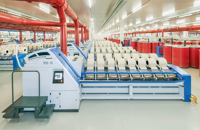
TRUeTZSCHLER TCO12
No of Doublings 8
Nips/minute:550nips/min.
Slivercount:3–6ktex(Ne0.2–0.1)
Lapdiameter:max.
650mm
Lap width:300mm
Maximumlapweight:25kg(net)
Laptubediameter:200mmBattweight:max. 80g/m
Feed:forward/backward
Ratchetwheels:16,17,18,20,22
Candiameter:600 mm, 1,000
mm1), 1,200 mm1) Can height(withcastors):1,200mm
Canchanger:above floor or
underfloor
Power consumption:5.7 kW (at 500nips)
Exhaustair:Central(aboveorunderfloor)
Can format mm
Length B
mm
Width A
mm
Width C
mm
600*
6,866
2,130
1,705
1,000**
7,044
2,680
2,440
1,200**
7,220
2,985
2,850
MARZOLI CM7
Speed up to 600 nips/min
Machine suitable for all cotton types
Eight combing heads
Grooved feeding roller driven on both sides to guarantee maximum feeding uniformity
Nipper in ultra light materials
Circular comb with combing angle of 90° and 4 sectors with different pin densities or with combing angle of 112° and 5 sectors
Constant narrow distance between jaws and circular comb thanks to standing-pendulum movement of the nipper
Wide variety of top comb needle densities: 23 - 26 - 29 - 32 needles/cm
Fluted biconical detaching rollers for perfect nipping on the entre width of the fringe
Stainless steel sliver tables to avoid false drafts
3 over 4 pneumatic drafting system located on the coiler to avoid false drafts
Quality control located after the drafting unit to monitor sliver evenness
Cans dimensions: 24" x 48"
Automatic can change
High efficiency motors
Main motor driven by inverter: acceleration, deceleration and machine speed set by HMI
Technical Data:
Circular comb
90° - 112°
Top comb
23-26-29-32 needles/cm
Can size
24" x 48"
Lap weight
80 g/m
Feed
Forward/backward
Noil
8% - 25%
Feeding rate
4.7 - 4.9 - 5.2 - 5.5 - 5.9 - 6.3
How does the material preparation affect Combing?
Parallelization of the Fibers in the Batt
The
degree of parallelization has a very great influence on the result of
the combing operation, both from the viewpoint of both economics and
quality. Very high level of parallelization also has adverse effect on
combing as that of poor parallelization. It is important to find the
optimum level of parallelization. Lack of parallelization and
longitudinal orientation, leads to elimination of longer fibers together
with the noil, as already explained. Loss of good fibers due to fiber
disorder is reinforced to the extent that the circular combs are
overloaded during passage through a disordered batt. Due to this, they
pluck and tear at the stock, thereby carrying away bunches of fibers.
Similar
phenomenon happens with an excessively thick batt. With same machine
settings, the amount of noil decreases proportionately with increased
parallelization of the fibers and with a decrease in batt thickness
(below the optimum). It therefore does not always mean that more noil is
automatically associated with better yarn quality. The correct goal is
always a predetermined waste elimination level.
On
the other hand, an understanding of the disadvantages of excessive
longitudinal fiber orientation needs a better understanding of the
combing process and in particular what is happening at the detaching
stage. While detaching, between one fifth and one sixth of the fibers
presented to the detaching rollers are drawn out of the batt. This means
only few fibers are drawn out of a thick layer of feedstock.
During
this stage, impurities, neps, foreign matter and so on are held back in
the sheet because of the retaining power of the thick layer. This
retaining power, and hence the so-called self-cleaning effect of the
batt, will be all the greater the higher the disorder of the fibers
within the sheet.
If
the fibers have an excessively high degree of parallelization, the
retaining power of the batt can be so severely reduced that it is no
longer able to hold back the neps as it usually does. Some of these neps
also pass through the top comb. Neppiness of the product is increased.
A
second disadvantage is that if the fibers are too highly ordered, the
single layers of the lap do not hold together well (it lacks cohesive
strength of the layers compared with that of the fiber-to-fiber adhesion
at the surface of the lap layers) and mutual separation layer from
layer is disturbed.
A
high degree of parallelization always leads to considerable hairiness
of the lap. Furthermore, the lap weight must be kept low. The degree of
parallelization depends on the total draft between the card and the
comber.
Batt Thickness (weight)
The
self-cleaning effect of the batt exerts a considerable influence on the
combing operation. This effect arises from the retaining power of the
fibers relative to impurities, which depends not only on the disorder of
the fibers but also on their quantity. A thick batt always exerts
greater retaining power than a thin one. At least up to a certain level,
the clamping effect of the nippers is also better with a higher batt
volume.
Adversely,
a thick batt always exerts a heavy load on the comb and this can lead
to uncontrolled combing. In this case, the fiber farthest from the
circular combs (upper side of the nipped web) may escape the combing
operation, since the combs are no longer able to pass through the whole
of the layer.
The
unfavorable effect of overloading the comb is greater than the
favorable effect of the retaining power of the sheet. A compromise must
therefore be struck between quality and productivity. Depending on
staple length (and Micronaire value), the ideal batt weight lies between
72 and 80 ktex for short and medium staple cotton, and between 64 and
74 ktex for long staple cotton, for fibre length longer than 1 ¼ inches.
Evenness of the Batt Sheet
The
more even the batt sheet (web) is across its width, the better the
clamping effect at the nipper clamping line. Evening-out of the web is
therefore of considerable significance. It is very important that the
slivers are arranged neatly relative to one another and evenly over the
entire working width at the lap machine.
The
most effective method of obtaining a high degree of evenness of the
sheet is high doubling in sheet form, as in the classical system, a
combination of sliver lap machine and ribbon lap machine (Fig. 4).
In
this respect, the operation of the ribbon lap machine was always ideal
in the past. Nowadays, however, the disadvantages far exceed the
advantages, e.g. the very high fiber parallelization. Caused by the high
drafts in two stages, resulting in insufficient cohesion of the sheet.
It does not permit high speeds and therefore high productivity compared
with the sliver lap system. The self-cleaning effect also suffers from
this high degree of parallelization.
The Disposition of the Hooks
Fibers
must be presented to the comber so that leading hooks predominate in
the feedstock. This influences not only the opening out of the hooks
themselves, but also the cleanliness of the web. If the batt is fed in
the wrong direction, the number of neps rises markedly. It also
increases the soiling and loading of top combs and circular combs, and
finally the neppiness.
Both
quantity and form of fiber hooks depend mainly upon the stiffness of
the fibers; the latter rises to the second or third power with
increasing coarseness of the fibers (Micronaire value). The hooks also
display different forms; fine, long fibers will always exhibit more and
longer hooks (horseshoe shape) than short, coarse fibers (hockey-stick
shape).
The
role of fiber hooks in the spinning process therefore becomes more
significant as fibers become finer. When short fibers are being spun,
fiber hooks are of secondary importance.
PREPARATION OF THE STOCK FOR COMBING
Outline
In general, two systems are still in use
Conventional web doubling process employs a sliver lap machine followed by a ribbon lap machine (Fig. 8, 9, 10) but ;today modern machine has mostly two passage (Fig. 5)
sliver
doubling process, in which a normal draw frame (without leveling)
provides the first passage and a sliver doubling machine follows as the
second passage
Fig. 5 – Overview of the two laps forming processes in use
Conventional System :
In this process the sliver lap machine (Fig. 6, 7) is
the first step machine in which. 24 slivers from the card are usually
fed together and side by side over a table into a drafting arrangement.
By
this process a loose form of web is created with a small draft of
around 1.5. After pressing and smoothing, this web is rolled up to a lap
by calendar rollers.
Fig. 6 – Top view of a sliver lap machine
Fig. 7 – Sliver lap machine
Fig. 8 – Elements of a ribbon lap machine
Fig. 9 – Ribbon lap machine
Fig. 10 – The ribbon lap machine – cross-section
Modern Preparation System :
The first machines using this system :
Fig. 11 – Basic design of the former (lap forming machine)
Fig. 12 – Web Former
The
idea of creating a comber feeding lap by a single web forming process
directly in front of the comber using a draw frame passage in front of
this web former, is developed in 1948 by a Company, called the super lap
machine.
Although
all later machines are of different designs they all are based on this
idea. That is why modern high-performance preparation systems will now
be explained on the basis of the machinery manufacturers machines,
starting with the first designs.
As
already mentioned, the web former (e.g. Web Former) always follows a
normal draw frame. On the Web Former machine the material flow starts
with the creel 1(Fig.11 & 12) , consisting of two feed rails. In normal operation 12 cans are laid out under each roller-assisted feed table.
Altogether,
finally gives a total of 24 doublings. The pre-draw frame slivers run
over a guide bridge above the service alley and also over several guide
rollers to the drafting system at 2(Fig. 11 & 13) .
The web created by the draft of 1.3 to 2.5 passes over two deflecting plates (Fig. 8)
onto the web table on which the webs are superimposed. Calendar rollers
draw these superimposed webs from the table to the lap winding
assembly.
The
strong compression created between the calendar rollers forms a new
web, which is rolled into a lap in the lap forming assembly.
Empty
tubes are automatically exchanged for full laps. Transport of the laps
to the combing machine is semi-automatic or fully automatic.
In-feed :
Fig. 13–The drafting arrangement of a Web Former
The
first part of the machine is a creel on each side material is feed
using two drafting arrangements from maximum. 28 cans obtained from the
draw frame.
Here also the slivers are guided over a service alley (one on each side) to the drafting arrangement (Fig.13).
The Web Former machine features a 3-over-3 roller, two-zone drafting arrangement
The pneumatically weighted top rollers can be continuously adjusted from minimum to maximum per top roller.
Draft distances are individually variable, and the draft levels in each of the break and main draft zones are also variables.
Upper and lower clearer aprons in combination with a suction system keep the rollers clean.
The
easily accessible drive for the drafting arrangement is in an enclosed
housing and is fitted with appropriate change gears and oil spray
lubrication.
The Lap Winding Assembly – Conventional System :
After passing through the web table, web runs through four calendar rollers (Fig. 14, 1). The pressure generated by two membrane cylinders can be adjusted up to 16 000 N.
The
calendar rollers are followed by two winding rolls (2) and a lap tube
holding device (3) with a lap weighting device. Final lap is obtained
through calendaring process and quality of lap depends on lap winding
assembly.
The
required weighting pressure (up to 10 000 N), derived from a piston, is
transferred via a pivoting lever to the weighting frame and thus to the
lap tube.
The Web Former has an automatic lap pressure control which adapts the pressure according to the lap diameter.
This is due to increase in diameter of the lap raises the weighting frame, so that pressure increases according to the diameter.
The
increasing size of the lap is adjusted using setting screws. The
machine stops when a preset lap length is reached, whereupon an
automatic device replaces the full lap by an empty tube.
Fig. 14 – The lap winding device of Web Former
Former speed control arrangement on the Web Former :
Fig. 15 – Speed diagram of the Web Former, Production gain by speed control
In
the former system the Web Former machine did not run at constant speed,
since this would mean choosing the speed according to the most critical
phase of lap winding, i.e. when lap winding was close to completion.
However,
this meant losing productivity. That is why machinery manufacturers
adapted the speed of the machine to the buildup of the lap by means of
the speed control set (Fig. 15).
So, for example, if a final speed of about 70 m/min was required, the machine started with a speed of 140 m/min.
System Incorporating the Latest Technology :
Since
production speeds using the winding system based on calendar rollers
have reached their limit due to the system itself, machinery
manufacturers developed a new lap winding system (Fig. 16).
The new lap winding system makes use of a unique belt tension and pressure arrangement.
The winding belt (Fig. 17, 1),
with a width similar to that of the laps, surrounds the lap to form a
circumferential pressure area (modern-shaped) ranging from 180° to 270°
from starting to full lap.
Fiber
guidance and pressure distribution applied by the modern principle
allow constant production (i.e. constant speed during winding of the
lap) at speeds of up to 180 m/min over the entire lap buildup.
Fig. 16 – Comparison between different winding systems
Fig. 17 – Modern winding process
Feature of Comber:
In
lap preparation, total draft, fibre parallelisation, no of doublings,
lap weight etc should be done properly (based on trial).
Higher the lap weights (gm/m) lower the quality. It depends on type of comber & fibre micronaire.
If finer micronaire is used, lap weight is reduced to improve combing efficiency.
If coarse micronaire is used, lap weight is also increased.
If
fibre parallelisation is too much, lap sheets sticking to each other is
more (It happens if micronaire is very low also). If lap sheets are
sticking to each other, total draft between carding & comber are
reduced.
If draft is less, fibre parallelisation is also less, hence loss of long fibres in noil will be more.
Top comb penetration should be highest for better yarn quality. But care should be taken to avoid top comb damage.
Damaged top comb will affect the yarn quality very badly.
Setting between unicomb & top nipper should be same & it should be around 0.40-0.5mm.
Feed weight is about 50-58gm for combers like E7/4 & is 65-75 gm for combers like E62 or E7/6.
The
lower the feed length, the better the yarn quality. Trials to be
conducted with different feed lengths & it are decided based on
quality & production requirement.
Required waste should be removed with the lowest detaching distance setting.
For
cottons with micronaire up to 3.5, top comb should have 30 needles/cm
& for cottons with more than 3.8 micronaire, top comb should
have 26 needles/cm.
Trials to be conducted to standardise waste percentage.
Piecing wave should be as low as possible & index should be decided based on cotton length & feed length.
Spectrograms should be attended. Comber sliver Uster should be less than 3.5.
Head to head waste% should be as low as possible.
Variation in waste percentage between combers should be as low as possible(less than 1.5%).
If cotton with low maturity coefficient is used, it is better to remove more noil to avoid shade variation problem.
Advantages of the Spinning Process:
This machine improves uniformity and strength.
This machine produces higher count of yarn.
It reduces neps in the yarn combe.
It improves smoothness and luster of yarn.
It improves the spinning value of fiber.
It combe yarn.
It produces much clearer yarn and reduces the hairiness of yarn.
Feature of Spinning Can for Combed Yarn:
Made to exact dimensions to meet industry requirement’s.
Top
quality anti static polyethylene sheet for cans, and strong, uniform
“jupee” fiber sheet for fiber cans, ensures uniform quality and
thickness of the can wall.
Meets the tough requirement’s of advanced spinning technology.
Spinning can made from special high carbon steel.
Specially heat-tempered for combed yarn can
Coils engineered in varying diameters to nest within themselves, thus providing additional capacity when can is full.
Dimensionally and geometrically accurate; consistent in every respect.
Calibrated for precise silver weight control.
Custom made to each customer individual Spring can system. Pressure and right requirement’s.
All Spring can system design to significantly reduce waste.
High impact on nylon wheel for combed yarn can
Non rotating dusts shields reduce up between
Combed yarn wheels and truck assembly.
SPECIFICATIONS OF LATEST COMBERS OF DIFFERENT MAKES
RIETER E 86
Technological data
E 86 with ROBOlap
E 86
Raw material, commercial staple
1
- 1 1/2 ( - 1 3/4) inches
Batt weight
(60) 64 - 80 g/m
LapWeightmax.
Diameter max. Width
21 kg
25 kg
combined with OMEGAlap E 36
25 kg
550 mm
580 mm
combined with OMEGAlap E 36
650 mm
300 mm
Noil extraction
8 to 25 %
Doubling
8
times
Draft
9.12 to 25.12 times
Sliver weight in runout
3
to 6 ktex
Efficiency
up to 96 %
up to 94 %
Max. production
90 kg/h
90 kg/h
Technical Data
Max. nip
550 min -1
Frequency
50 Hz
60 Hz
50 Hz
60 Hz
Installed
power
-total
-with fibreseparator
6.95 kw
–
7.95 kw
–
6.65kW
9.65kw
7.15kw
9.35kw
Power consumption
-total
-with fibreseparator
4.7 kw
–
5.38 kw
–
4.5kw
4.6kw
4.84kw
5.00kw
Machine data
Type of feed
Forward
run / return run
Feed distance moved per cycle
4.3 / 4.7 / 4.95 / 5.2 /
5.55 / 5.9 mm
Ri-Q-Comb circular comb
i400, i500, i700
Ri-Q-Top top comb
26, 30 teeth/cm
Drafting system
3
over 3 with variable front zone and main zone distance
Can diameter
600 mm, 24 inches / 1 000 mm, 40 inches
Can height including rolls
1 200 mm, 48 inches
Machine distance with SERVOtrolley
600
mm cans min. 3 000 mm (zero line-zero line) / 1 000 mm cans min. 3 500 mm
(zero line-zero line)
Machine distance with SERVOlap
600
mm cans min. 2 800 mm (zero line-zero line) / 1 000 mm cans min. 3 500 mm
(zero line-zero line)
Lap transport system
-SERVOtrolley E 17(semi-automated)
-SERVOlap (fullyautomated)
-SERVOtrolley E 16(semi-automated)
-SERVOlap (fullyautomated)
Noil extraction
-central suctionsystem
-separate lap suction
system,automated
-central suctionsystem
-fibre separator,continuous
Port to SPIDERweb
optional
TRUeTZSCHLER TCO12
No of Doublings 8
Nips/minute:550nips/min.
Slivercount:3–6ktex(Ne0.2–0.1)
Lapdiameter:max.
650mm
Lap width:300mm
Maximumlapweight:25kg(net)
Laptubediameter:200mmBattweight:max. 80g/m
Feed:forward/backward
Ratchetwheels:16,17,18,20,22
Candiameter:600 mm, 1,000
mm1), 1,200 mm1) Can height(withcastors):1,200mm
Canchanger:above floor or
underfloor
Power consumption:5.7 kW (at 500nips)
Exhaustair:Central(aboveorunderfloor)
Can format mm
Length B
mm
Width A
mm
Width C
mm
600*
6,866
2,130
1,705
1,000**
7,044
2,680
2,440
1,200**
7,220
2,985
2,850
MARZOLI CM7
Speed up to 600 nips/min
Machine suitable for all cotton types
Eight combing heads
Grooved feeding roller driven on both sides to guarantee maximum feeding uniformity
Nipper in ultra light materials
Circular comb with combing angle of 90° and 4 sectors with different pin densities or with combing angle of 112° and 5 sectors
Constant narrow distance between jaws and circular comb thanks to standing-pendulum movement of the nipper
Wide variety of top comb needle densities: 23 - 26 - 29 - 32 needles/cm
Fluted biconical detaching rollers for perfect nipping on the entre width of the fringe
Stainless steel sliver tables to avoid false drafts
3 over 4 pneumatic drafting system located on the coiler to avoid false drafts
Quality control located after the drafting unit to monitor sliver evenness
Cans dimensions: 24" x 48"
Automatic can change
High efficiency motors
Main motor driven by inverter: acceleration, deceleration and machine speed set by HMI
Technical Data:
Circular comb
90° - 112°
Top comb
23-26-29-32 needles/cm
Can size
24" x 48"
Lap weight
80 g/m
Feed
Forward/backward
Noil
8% - 25%
Feeding rate
4.7 - 4.9 - 5.2 - 5.5 - 5.9 - 6.3
Speed
Up to 600 nips/min
Lap weight
Up to 80 g/m
Production
Up to 85 kg/h
Self cleaning top comb
Automaic lap piecing
LMW LK69
Comber LK69 with “PACT”, “Sets the pace”, in the combing technology
with a production of up to 2.1 Tons/day @ 600 npm. The kinematical
linkage syntheses for synchronized and optimal movement of parts ensure
gentle handling of heavier laps. The optimal selection of fibre enables
the machine to run at higher speeds without straining the fibre and
ensure efficient removal of short fibres.
Machine Data
No. of heads per machine : 8
Maximum lap diameter : Upto 650 mm
Width of lap : Upto 300 mm
Nips per minute : Upto 600
Delivery can size (Dia. x Ht.) : 24” x 48” (600 mm x 1200 mm)
: 40” x 48” (1000 mm x 1200 mm)
Main motor : 4 kW
Brush motor : 1.1 kW
Control panel : 0.24 kW
Total installed power : 5.34 kW
Compressed air requirement : 0.4 Nm3/hr @ 6 kg/cm2
Exhaust air : 0.7 m3/sec
Sources :
W. Klein, “Technology of Short Staple Spinning”, The Textile Institute, Manual of Textile Technology, All volumes.
Carl A. Lawrence , “ Fundamentals of Spun Yarn Technology”, CRC Publications, 2003.
P.R. Lord, Hand Book of Yarn Production : Science, Technology and Economics, Tailor and Francis, 2003.
Eric Oxtoby, “Spun Yarn Technology”, Butterworths, 1987.
NCUTE publications on Yarn Manufacturing, Indian Institute of Technology, Delhi.


.jpg)