Energy efficiency Layout of Spinning Mill


There are different types of layout for spinning mills which varies from Architect to Architect or Textile/Project Consultant.
It is also observed that basically the layouts/drawings of building and M/c layout is prepared and finalized by concern authorities and then Electrical Consultant is introduced in the picture. When the final drawings is kept in front of Electrical Consultant, he had not much choice for selection of place for substation transformer etc. Then he tries to utilize available space.
Initially spending some amount the spinning mill is started, after that the major recurring expenses are electrical bills that is electrical consumption. As per SITRA Norms the unit consumption for spinning mill is 3.564 units (KWH)/kg of yarn.
Now the question is whether the spinning mill’s specific consumption is in the tune of SITRA norms? If yes then you have to accept that the electrical layout of that mill is in order and if not then one has find the reason for that. This specific consumption is directly related with the electrical design and not related to the type of layout, type of building, type of insulation and type of structural design etc.
Hence Electrical design plays a major role in the project of spinning mills because it is directly related to the recurring expenses. The purpose of this article is to develop a new concept for electrical layouts as well as layout of spinning mill.
Now every spinning mill had started energy auditing and started adopting necessary positive changes in electrical system and found that so much energy is saved.
This can be said in the other words, that old mistakes have rectified upto certain level. But prevention is always better than cure. So at least in future the responsibility of electrical consultant increases in designing of electrical layout of spinning mill and he should take adequate care and have a different vision to achieve the target of energy efficient electrical design. He should be sure that his electrical design shall be such that the specific consumption of the spinning mill shall be within SITRA norms or below the norms.
For the concept of designing energy efficient layout of spinning mill. One has to compromise certain things like Architectural vie front elevation etc. Which are not at all related to recurring expense because day today electrical unit charges will go up. So this is a high time to decide whether you have to run your mill with low specific consumption or your outer look out of mill shall be good irrespective of its high specific consumption.
ELECTRICAL CONSUMPTION
Let us bifurcate the total consumption as follows.


CS electric
 . .   |
| Add caption |
There are different types of layout for spinning mills which varies from Architect to Architect or Textile/Project Consultant.
It is also observed that basically the layouts/drawings of building and M/c layout is prepared and finalized by concern authorities and then Electrical Consultant is introduced in the picture. When the final drawings is kept in front of Electrical Consultant, he had not much choice for selection of place for substation transformer etc. Then he tries to utilize available space.
Initially spending some amount the spinning mill is started, after that the major recurring expenses are electrical bills that is electrical consumption. As per SITRA Norms the unit consumption for spinning mill is 3.564 units (KWH)/kg of yarn.
Now the question is whether the spinning mill’s specific consumption is in the tune of SITRA norms? If yes then you have to accept that the electrical layout of that mill is in order and if not then one has find the reason for that. This specific consumption is directly related with the electrical design and not related to the type of layout, type of building, type of insulation and type of structural design etc.
Hence Electrical design plays a major role in the project of spinning mills because it is directly related to the recurring expenses. The purpose of this article is to develop a new concept for electrical layouts as well as layout of spinning mill.
Now every spinning mill had started energy auditing and started adopting necessary positive changes in electrical system and found that so much energy is saved.
This can be said in the other words, that old mistakes have rectified upto certain level. But prevention is always better than cure. So at least in future the responsibility of electrical consultant increases in designing of electrical layout of spinning mill and he should take adequate care and have a different vision to achieve the target of energy efficient electrical design. He should be sure that his electrical design shall be such that the specific consumption of the spinning mill shall be within SITRA norms or below the norms.
For the concept of designing energy efficient layout of spinning mill. One has to compromise certain things like Architectural vie front elevation etc. Which are not at all related to recurring expense because day today electrical unit charges will go up. So this is a high time to decide whether you have to run your mill with low specific consumption or your outer look out of mill shall be good irrespective of its high specific consumption.
ELECTRICAL CONSUMPTION
Let us bifurcate the total consumption as follows.
Let
us consider the basic consumption i.e. actual M/cs consumption as fixed
then B,C,D,E & F components are directly proportional to recurring
expenses. Humidification is the independent subject, hence remaining
components C,D,E & F is the only area where the skill is to be
utilized in electrical design.
CABLE LOSSES :-
1) The cable losses are directly proportional to the length.
2) The losses are proportional to the square of current.
Hence for energy efficient electrical design the main concept in the mind should be that there will be minimum cable length. Hence the selection of panel board position and main panel room and transformer location is very important.
KEY POINT TO REDUCE CABLE LENGTH
Study the common main cable path and try to reduce the common path. (Fig.1.0)
Reduced the common path leads to reduce main cable length.
Use of HT Cable to reduce the length of LT cables, because the current at HT side is very low compare to LT side and since it is proportional to the square of current try to provide transformer nearer to LT Panel.
SELECTION OF L.T. CABLES
This is an independent subject, hence it is very important to select the rating of cables required. The main aspect for selection of cable size is voltage regulation. The variation or voltage regulation should not be more then + or – 2.5% between two far ends.
For Example : For particular current one had selected 240 Sq.mm and cable length is say 85 mtrs. For another feeder assume that the current is same but the length of cable is say 120 mtrs., then one has to calculate the available voltage at the far end and whether it is in the tolerance or not if not then he may require to select the cable of higher size.
The thumb rule should not be applied while selection of cable. If you increase the size of cable then cost also increases but losses reduce if you reduce the size of cable then cost decreases but losses increases. Hence the study of cable economics is very important (Fign. 1.1).
The
location of transformer should be nearer to the main LT panel and always
prefer to connect the transformer by LT bus duct of sufficient size to
main LT panel. Some time the availability of outer space is not possible
for transformer and substation then indoor type transformer to be
preferred and these may be placed just outside of the LT room or
adjacent to the LT room or in LT room and we can place the substation
suitably nearer available space and the HT side may be terminated by HT
cables. If required then HT indoor breakers can be used for protection
of transformer ( fig. 2.1).
All above points are pertaining to reduce the possible cable losses.
TRANSRORMER LOSESS
Let us calculate the commercial effect of 1 KWH i.e. 1 unit per Hour.
1x24 Hrs x 350 day = 8,400 Units x 3.15 = Rs. 26,460.00
i.e. saving of 1 unit in transformer will lead to saving of Rs. 26,460.00 per ear.
While selecting the transformer the technical specification are to be carefully studied the selection of transformer should not be on commercial terms but it should be combination of both i.e. commercial and technical.
Now there are some manufacturers who manufacturers low loss transformer with some additional cost. Since the losses are directly proportion to the square of the current, the transformer of higher rating shall have low losses but the cost will high.
Hence it is important to calculate the losses of transformer for the actual working load and accordingly one can easily decide the rating and selection of transformer. Another aspect of transformer selection is magnetizing current generally all manufacturers specify this below 3% but some manufactures specify 1.5% or 1.25% also, then it is very important to know the commercial effect of magnetizing current. (fig. 1.3)
The
transformer with high magnetizing current will draw more reactive
current and to compensate this, more shunt capacitors are required to
improve power factor. The transformer with low magnetizing current will
draw less reactive current and hence lesser shunt capacitors shall be
required to compensate power factor and there will be saving in cost of
additional capacitors, switching devices required for additional
capacitors, cost of cable required for connecting the additional
capacitors and besides that the self consumption of additional
capacitors (Fig. 1.4).
Hence selection of transformer is very important to control the recurring expenses.
The major two aspects for electrical designing of spinning mill is covered. Now another important subject directly related to recurring expenses is Illumination system. Use of Electronic Ballast definitely saves about overall 35% energy bill in illumination system but unfortunately there are only very few manufacturers who’s electronics ballasts are successfully working. In some cases it is observed that problems in 40W tube arises oftenly by using electronic ballast hence it is also very important to select the electronic ballast as well as tube. If the above things are followed it is possible to achieve the specific electrical consumption not only in the limit of norms but below of that.
General electrical terms, we have studied towards energy efficient electrical design.
LAYOUT OF SPINNING MILL :
To achieve some thing our view towards that subject should be wide and without preconcept (traditional). One should not compare with other existing systems. But he should look through the other angle to achieve the target.
Let us study the general types of layout of spinning mill. Generally we can divide the spinning mill in two types. One is H. Plant at one side and second is H. Plant at two sides. i.e. for 25,000 spindles and 12,500 spindle x 2 spindles respectively.
Now let us study the probable location of L.T. Room and PDB’s.
In this
Fig. 2.0 you will observed that comparatively “B” location of LT room is
near the load centre but main draw back is the PDB of H. Plant is far
way @ more than the 65 mtrs.
In this
Fig. 2.1 you will find that at “A” or “B” position is near the load
centre but the main cable running for other side of PDB’s increases.
In this
Fig. 2.2. it is seen that all PDBs are placed in the centre and location
of L.T. Room is at “A”. Here it is observed that the cable length is
minimum. Electrically this is comparatively energy efficient layout. The
main panel should be the as near as load centre, Since the major load
is at ring frame the ideal design shall be near the Ring Frame that is
load centre. Considering the above aspect the following layout is
prepared. Now whether it is practically workable or not it is to be
discussed with concern authorities but as a technical person anybody had
to accept that this shall be the ideal electrical design for spinning
mill.
A – L.T. Panel
B & C – Compressor Room for Prep. & Ring Frame respectively.
Generally both side H. Plant are preferred for initial cost and convenience. In fig. 2.3 the location of L.T. Room is just nearer to the ring frame trench i.e. PDB of Ring Frame and Post Spinning. If possible transformer can be erected in the room or just outside of the post spinning as shown.
A typical layout shown in fig. 2.4 in which an open space is shown open to sky. The L.T. Room is adjacent to Ring Frame and Post Spinning section two locations of compressor room is also shown. Compressed air is very energy intensive only about 5% input electrical energy is converted to useful energy and rest is loss as heat. Use of compressed air for clearing is rarely justified. If pressure requirements are widely different e.g. 3 Kg/Cm2 then it is advisable to have two separate compressor system and the location of compressor is preferably near the load centre, hence the two separate compressor room have shown in fig.2.4. This may increase the overall efficiency of Air system. Now let us see the utility of open space which is open to sky. If we can provide the double glass framed window for the both sheds towards open to sky side the utilization of day light will definitely save in lighting consumption at least in day time.
Hence considering major recurring expenses of electrical losses, efficiency of air system, optimum utilization of natural light. This energy efficient layout of spinning mill is prepared.
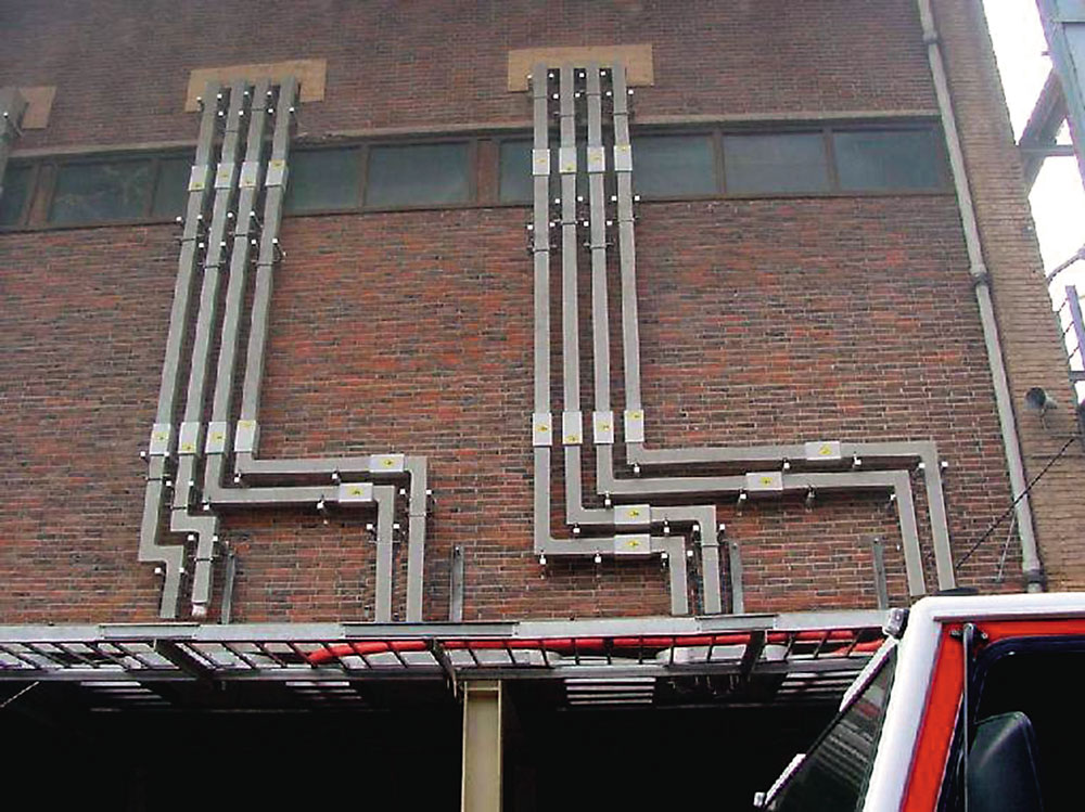
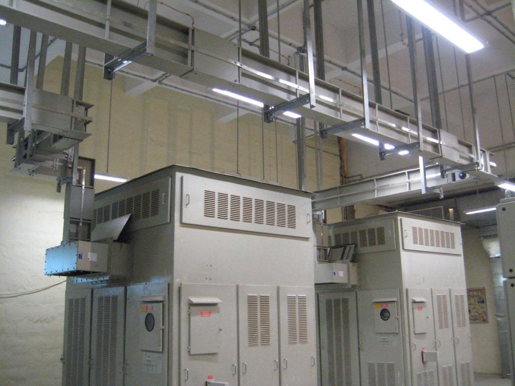
Present day world the cables are replace by Bus Bar trunking.
busbars are usually made out of aluminium or copper and they are able to conduct electricity to transmit power from the source of electric power to the load. They are usually supported by insulators and conduct electricity within switchboards, substations or other electric apparatus. Some typical applications of these devices can be to form the interconnectedness of the incoming and outgoing electrical transmission lines and transformers at an electrical substation; supplying huge amounts of amperes to the electrolytic process in an aluminium smelter by using large busbars and also interconnecting generators to the main transformers in a power plant.
When comparing the total estimated cost of the power supply system with cabling and trunking using the same user, the cost of installation and materials system not only exceeds the cost of cabling, but in some cases much lower, and taking the time factor into account, busbars are simply irreplaceable. Below are some of the benefits.
References
Veejhay B Limaye of Miraj
B & C – Compressor Room for Prep. & Ring Frame respectively.
Generally both side H. Plant are preferred for initial cost and convenience. In fig. 2.3 the location of L.T. Room is just nearer to the ring frame trench i.e. PDB of Ring Frame and Post Spinning. If possible transformer can be erected in the room or just outside of the post spinning as shown.
A typical layout shown in fig. 2.4 in which an open space is shown open to sky. The L.T. Room is adjacent to Ring Frame and Post Spinning section two locations of compressor room is also shown. Compressed air is very energy intensive only about 5% input electrical energy is converted to useful energy and rest is loss as heat. Use of compressed air for clearing is rarely justified. If pressure requirements are widely different e.g. 3 Kg/Cm2 then it is advisable to have two separate compressor system and the location of compressor is preferably near the load centre, hence the two separate compressor room have shown in fig.2.4. This may increase the overall efficiency of Air system. Now let us see the utility of open space which is open to sky. If we can provide the double glass framed window for the both sheds towards open to sky side the utilization of day light will definitely save in lighting consumption at least in day time.
Hence considering major recurring expenses of electrical losses, efficiency of air system, optimum utilization of natural light. This energy efficient layout of spinning mill is prepared.
Present day world the cables are replace by Bus Bar trunking.
Busbar Trunking System
This is the is a system of distributing electric power using copper or aluminium busbar with suitable enclosures and good amount of protection to prevent the cables from getting damaged due to foreign bodies.
Busbars are now becoming irreplaceable simply because of the convenience and safety factor. While using traditional cables, the cost of cabling and trunking and the time taken for installation is much higher than busbars as well.
Installing busbars over conventional cabling has a range of advantages some of which are mentioned below:
Design: Busbars have a compact design through which compressed flat conductors can pass through the enclosure. Due to the compact designs, busbars require lesser space than traditional cabling systems and this is a major advantage when thousands of amperes of electricity need to be transmitted.
Heat Absorption: Since the design is compact and has a metal casing with well-defined surface, busbars can absorb heat generated while transmissions and distribution of electricity in the walls of the enclosure. The system of cooling is much better than traditional cabling system.
Flexibility: Busbars are more flexible in nature compared to cables in the sense that it can be used in any kind of structure with any configuration. They are easily modifiable and hence the addition of an extra room or building can be easily done. Busbars can also be relocated without much of a capital expenditure.
Cost Savings: Busbars can be mounted easily than a cable and incurs a lesser cost of installation than traditional cables. They can also be mounted at a lesser time than traditional cables.
Better Resistance: Busbars have rigid design elements and hence has better resistance than cables, especially in case of short circuits. Busbars have a minimum distance between the conductors which in turn reduces the induction of resistance. Busbars also have a thin and flat tire which helps in optimal distribution of density of current and in turn reduces resistance. Due to lower levels of density, voltage loss is much lower than cables for the same length.
Reduced Loss of Energy: Busbars have lower resistance than cables. Hence the loss of energy due to transmission and distribution is lower in Busbars. Busbars also have a limited growth of reactive power to operate compared to cable systems.
Lower Electromagnetic Field: Due to the compact design and the steel shell, a comparatively lower electromagnetic field is created around a Busbar as compared to a cable. Hence, high loads of 4000 ampere to 5000 ampere can easily be created near the data cables which is free from electromagnetic interference.
No Dependency on Length: In case of traditional cables connecting a phase with high amperage, the length of the cables varies both on location and connection. But in case of Busbars, the difference of length is eliminated since they have the parameters of active and inductive resistance to ensure that the load on each phase is equal.
Ease of Distribution: Busbars help in easy, efficient and safe distribution of line with the junction boxes in places where they are required. Moreover, the location data junction boxes can be changed whenever and where-ever in the future. The junction boxes can be easily increased in the future as well with busbars.
Standard Cells: Fully certified standard cells are an integral part of busbars which is meant to eliminate human error. Examples of such standard cell include junction boxes and plugs. These are certified parts of busbars which meet all kinds of safety standards.
Safe and Secured: Busbars are fitted with a steel casing and cannot be damaged by rodents as compared to cables.
Apart from the above, there are a variety of other advantages that busbars have over cables. With the network and distribution requirement growing day by day, traditional cables will soon be history and busbars will continue to gain importance.
Busbar Trunking Vs. Cables
| S.No | Busbar Trunking | Cables |
|---|---|---|
| I | Features: | |
| Finishing is very good, hence adds to aesthetics of building | Improper laying of the cables may spoils the aesthetics of building | |
| Multiple floor building power feeding can be done with single Bustrunking system | Multiple floor building power feeding has to be done with multiple cable sets. This make the complete system cumbersome. | |
| Power tap off can be done from the single system installed.. Incase the load changes we have to just replace the Tap off boxes of higher rating. | Not possible. Additional cables to be laid till the particular floor. | |
| II | Voltage Drop : | |
| The voltage drop of bustrunking is less as compared to cables. | The voltage drop is more in cables. | |
| III | Structure : | |
| Example for 3200A(Cu) dimensions : 151(w)x340(h) and light in weight | Cables and its structure 700mm wide i.e., cable tray etc. is very heavy and occupies more space. | |
| Total run is made up of multiple element which are joint together. Thus making the complete system maintenance friendly. | As single length of multiple cables are installed, making it maintenance nonfriendly. | |
| Easy retrofitting of the element is possible in case the location and consumer load | Easy retrofitting of the element is not possible in case the location and consumer load | |
| Totally enclosed, cannot be tampered. Fit and forget system2 | Insulation can wear off with time. Can get damaged by rodents. Has to maintained on regular basis. | |
| IV | Degree of Protection : | |
| IP-54 for plug in type, IP55, 65 for feeder | No protection as such | |
| Special protection is to be taken for installation in OUTDOOR area. | Special protection is to be taken for installation in OUTDOOR area. | |
| V | Enclosure : | |
| It consists of busbars in a protective enclosure, including straight lengths, fittings, devices and accessories. | Cables are simply insulated with multiple layers of PVC. | |
| High Short circuit strength & high fire protection | Low Short circuit strength & low fire protection | |
| VI | Termination : | |
| Direct termination through busbars | The method for cable termination is very cumbersome. | |
| Termination is simple and easy. | Additional supports are required to hold the cables inside the panel. | |
| Have a highly compact structure and can be bent up to 90 degree. | Cables are generally installed in bundles & with such a cross section that they can not be bent tightly. | |
| VII | Time & cost consumption : | |
| When sizing busbars the designer only needs to make calculations on a single riser which reduces design time and costs. | It is necessary to protect each cable individually with a fuse and when laying the cables in bundles it is necessary to anchor them properly so that they can withstand the electrodynamic forces generated in the event of a short ckt. So, the designers have to spend more time on calculations. | |
| VIII | Use of additional items : | |
| No additional supports are required. | Heavy labor is required to lay the cables | |
| No extra holes/cutouts are required. | Holes to be made in the gland plate for fixing cable glands | |
| No cable tray is required, supported on ceiling / wall. | Cable tray or the digging of the trench is required to lay the cables | |
| No special tools are required. | Special tool are required for crimping the cable lugs | |
| Design verified switchgear assembly, limits from manufacturer’s catalogue | Limits depend on the laying method and cable accumulation. The derating factor must be determined / calculated | |
| IX | Halogen Free : | |
| Principally free from halogen. | PVC cables are not free from halogen. Halogen-free cables are very expensive. | |
| X | Damage by rodents : | |
| Busbar systems cannot be damaged by various rodents, which prevents the steel casing. | Cables can be damaged by various rodents. | |
busbars are usually made out of aluminium or copper and they are able to conduct electricity to transmit power from the source of electric power to the load. They are usually supported by insulators and conduct electricity within switchboards, substations or other electric apparatus. Some typical applications of these devices can be to form the interconnectedness of the incoming and outgoing electrical transmission lines and transformers at an electrical substation; supplying huge amounts of amperes to the electrolytic process in an aluminium smelter by using large busbars and also interconnecting generators to the main transformers in a power plant.
The size of the busbar determines its
application and the amount of current that it can carry safely. They can
be tubular, solid or flat depending on the application and to serve
different needs. A tubular busbar is hollow and this shape allows it to
dissipate heat more efficiently as it has a high surface area. Hollow or
flat shaped bus bars are prevalent in high current applications. Also,
the hollow section of a busbar is generally stiffer as compared to a
solid rod, thus this allows a greater span between busbar support in
outdoor switchyards. The smallest cross-sectional area of a busbar can
be as little as 10mm2, but electrical substations would make use of
busbars with a diameter of more than 50 mm as they carry great amounts
of amperes. Aluminium smelters would make use of these large busbars to
carry tens of thousands of amperes to the electrochemical cells that
produce aluminium from molten salts.
As they carry large amount of
electricity, it is important to support the busbars with insulation to
prevent any accidents from happening whereby someone may accidentally
touch the bus bar. Insulation can either support the busbar or
completely surround it. They can be prevented from accidental touch by
placing the bus bars at an elevated height so it would not be easily
accessible or by a metal earth enclosure. Some bus bars such as the
earth bus bar can be bolted directly into the housing chassis of their
enclosure. This prevents unwanted touch and also saves the bus bar from
any damage it may incur when left exposed. There are several other ways
that busbars can be connected to one another or the electrical apparatus
with which they would be used with such as by bolting, clamping or
welding connections. Switchgears, panelboards or busways usually contain
the busbars and the electrical supply is split by the distribution
boards into different circuits. Busways are a type of busbars that have a
protective cover and are long in shape. Also referred to as bus ducts,
these devices allow the electricity to branch out to different circuits
at any point along its surface; unlike regular busbars that allow
branching of the main supply only at one location.
The most common types of busbars present
in the industry today are rigid busbars, strain busbars and insulated
phase busbars. Each of these different types of busbars has different
applications and uses. The rigid busbars are used in low, medium or high
voltage applications, constructed with aluminium or copper bars and
they make use of porcelain to insulate them. As for the strain busbars,
they are mostly used in high voltage applications and are usually strung
between the metal structures of a substation. They are held in place by
suspension-type insulators. Lastly, as for the insulated-phase bus
bars, they are used at medium voltage and similar to the rigid bus bars,
they are rigid bars that are supported by insulators. These busbars are
able to eliminate short circuits between adjacent phases.
When comparing the total estimated cost of the power supply system with cabling and trunking using the same user, the cost of installation and materials system not only exceeds the cost of cabling, but in some cases much lower, and taking the time factor into account, busbars are simply irreplaceable. Below are some of the benefits.
- Busbars systems have a compact design. Compactness of the arrangement provide reliably isolated and tightly compressed flat conductors inside the enclosure. Bus systems require less space than the cable systems, especially at loads in the hundreds or thousands of amperes.
- Tightly compressed tires, enclosed in metal casing with a well-developed surface, can take a well-produced heat to the walls of the enclosure and from the environment. Cooling is better than cable systems.
- The modular design of busbar systems is flexible and mobile, allows you to apply it to buildings or structures of any type and configuration, with busbar systems, you can easily modify, add or move to another room, building, and reinstall it without any capital expenditure.
- Mounting willingness busbar systems is significantly higher than that of cable. This provides a much lower cost of installation and use less time while working on the tire mounting.
- The design stage of the building with bus systems:
- Reduce the number of cable trays;
- Decreases the number of switchboards, it becomes possible to connect loads (of the mechanisms on the floors, etc.) directly from the junction boxes;
- Decrease the size of the main switchboards;
- Reducing the number of circuit breakers;
- Excludes many accessories used for cable systems;
- Simplified design and reduced development time of the project;
- Additional automated design project, except the visibility, said of the system components and the specification of the project.
- Rigid design elements of the system provides increased resistance to short-circuit compared to cable systems (for example, busbar 3000A: 264 kA and 120 kA peak thermal value of the current short-circuit).
- The minimum distance between the axes of the conductors reduces the induction of resistance, and the flat, relatively thin tire contributes to the optimal distribution of current density in it (crowding-out effect at high current loads to the surface is peculiar and minimal to cable systems), which lowers resistance. As a result of low levels of resistance and impedance, voltage loss at one and the same length of busbar systems is significantly lower than in cable systems.
- Low resistance values in the busbar system helps to reduce the loss of active energy and limit the growth of reactive power to operate, compared to cable systems.
- Compact design and steel shell provides a significantly lower electromagnetic field around the bus system compared to c cable. Tire system of high load (4000A – 5000A) can be safely installed near the data cables and does not create electromagnetic interference in an information system.
- Typically, a particularly high amperage use multiple cables for connecting one phase, where the cables can vary both in length and at the location and connection. Busbar systems eliminate the difference in length between the conductors that have the exact parameters of the active and inductive reactance, and ensure that the load on each phase is maximum equal. Cable systems cannot be strictly parametrized.
- With busbar power system, it can be easily, efficiently and safely distributed on the line with the junction boxes in places where it is needed. Location data junction boxes can be easily and safely changed if necessary in the future. In addition, there is always the possibility of increasing the number of junction boxes.
- Bus systems consist of a fully certified standard cells, where everything is made to eliminate human error. For example, junction boxes and plugs are tested and certified parts of the busbar system and meet all safety requirements. The reliability of the adherence of all junction boxes are standardized and does not depend on the installation. Security Connection cable systems depends on the experience of the installer.
- Busbar systems cannot be damaged by various rodents, which prevents the steel casing, unlike the unprotected cable systems.
References
Veejhay B Limaye of Miraj
CS electric
1 comment:
Hi Prakash, Very nice an informative blog. We are pioneering implementation of energy measuring and monitoring tools with data analytics on the cloud. Can we get in touch to discuss further on its applications in spinning industry. Regards/Henry Dsa my email henry.dsa@nexnergy.com
Post a Comment