Process Control in Ring Frame
Latest Development in Ring Frame
Structure of Ring Frame Yarn Packages
Yarn Twist

Introduction
|
||||||||||||||||
The ring spinning machine was invented in the
year 1828 by the American Thorp. In 1830, another American, Jenk,
contributed the traveller rotating on the ring. In more than 150 years
that have passed since that time, the machine has experienced
considerable modification in detail, but the basic concept has remained
unchanged. Fig. 1 shows a typical ring frame.
|
||||||||||||||||
|
||||||||||||||||
The long central section of the machine, on
which production is actually carried out, consists primarily of
longitudinal members in the form of spindle rails and drafting rollers
extending over the complete machine length.
|
||||||||||||||||
These
longitudinal members
are secured to intermediate sections arranged at short intervals along
the machine length. The sections also serve as supports for the creel .
|
||||||||||||||||
The ring
spinning machine has been the most widely used form of spinning and it
will continue for some more time, because it has unique advantage over new spinning technologies:
|
||||||||||||||||
|
||||||||||||||||
For these reasons, new spinning processes
(with the exception of rotor spinning) have difficulty in gaining wide
spread acceptance.
|
||||||||||||||||
Disadvantages associated with ring spinning are:
|
||||||||||||||||
|
||||||||||||||||
In long
term, the ring frame can survive in longer term only if further success
is achieved in automation of the ring spinning process. Also, spinning
costs must be markedly reduced since this machine carries significant
cost factor in spinning mill.
|
||||||||||||||||
Operation of the Ring frame
|
||||||||||||||||
Task of the ring spinning
|
||||||||||||||||
|
||||||||||||||||
Principles of operation
|
||||||||||||||||
Fig. 2 shows the operating parts of the ring frame and the principle of operation is explained below:
|
||||||||||||||||
|
||||||||||||||||
|
||||||||||||||||
Cross-section of the machine
|
||||||||||||||||
Fig. 3
shows the cross-section of a typical ring spinning machine. The ring
frames are two sided machines with the spinning positions located on
both sides of the machine. Each spindle is a spinning position. The
spindle rail houses the spindles. The creel housing the feed roving
bobbins are arranged in two rows on each side of the machine. The
drafting arrangement is carried on the roller beams. Each intermediate
section stands on two feet adjustable in height by means of screws,
thereby permitting easy leveling of the machine.
|
||||||||||||||||
|
||||||||||||||||
In modern
machines, an auto-doffer is also provided. Including the auto-doffer,
the width of the machine varies from 800 to 1000 mm (up to 1400 mm when
the doffer arm is swung out). Today, the machine length can reach 50 m.
Spindle gauges usually lie between 70 and 90 mm.
|


The creel
|
|||||||||||||||||||||
In design terms, the creel is a simple device.
It can nevertheless, influence the performance of the machine as well
as the yarn quality by introducing number of faults. In particular, if
the roving bobbin does not unwind perfectly, then false draft can arise,
or in worst case it may lead to end breakage
|
|||||||||||||||||||||
|
|||||||||||||||||||||
To avoid this problem, the bobbin suspension holders are provided in the machine which is shown in Fig.1.
This is provided for each spindle. Each holder has in its lower portion
the actual retainer device for the bobbin tube. When the ring is pushed
up as far as it will go by the upper end of a tube inserted into the
holder, the bobbin retainer swings out; when the ring is pushed up for
second time, the retainer is retracted and the bobbin can be withdrawn,
for example when it is empty.
|
|||||||||||||||||||||
The holders are suspended on ball bearings. A
light brake arm presses gently against the bobbin to prevent it rotating
quickly. Modern creels take up a lot of space in breadth since very
large bobbins are used now.
|
|||||||||||||||||||||
The drafting arrangement
|
|||||||||||||||||||||
Influence on quality and economics
|
|||||||||||||||||||||
If the quality is taken as the sole criterion,
then the drafting arrangement is the most important part of the
machine. It influences mainly evenness and strength. The following
aspects are therefore of great significance:
|
|||||||||||||||||||||
|
|||||||||||||||||||||
However, the drafting arrangement also exerts
an influence on the economics of the machine – directly through the end
breakage rate, and indirectly through the draft level.
|
|||||||||||||||||||||
If higher
drafts can be set in the drafting setup, then coarser roving can be used
as feed stock. This implies a higher production rate at the roving
frame and thus a saving in roving spindles, i.e. a reduction in the
total no. of machines, space, personnel, and so on. On the other hand,
increase in draft usually adversely affect the yarn quality.
|
|||||||||||||||||||||
Draft limits in ring frame
|
|||||||||||||||||||||
|
|||||||||||||||||||||
The break draft must be adapted to the total
draft in each case since the main draft should not exceed 25 to 30.
Accordingly, normal break drafts are:
|
|||||||||||||||||||||
|
|||||||||||||||||||||
Design concepts in the structure of the drafting arrangement
|
|||||||||||||||||||||
The ring
spinning machines are fitted with 3 line double apron drafting
arrangements. They comprise of three lower fluted steel rollers to which
the drive is applied. Top rollers carried in a pivoted weighting arm,
are arranged above the fluted rollers and are pressed against them.
|
|||||||||||||||||||||
The strand
contains only few fibers when it reaches the main drafting field;
accordingly, this is provided with a guide device consisting of an upper
and a lower revolving apron.
|
|||||||||||||||||||||
|
|||||||||||||||||||||
Normally, the top rollers are arranged as shown in Fig.2(a).
The front top roller is set slightly forward by a distance relative to
the front bottom roller. While the middle top roller is arranged a short
distance behind the middle bottom roller. In each case the distance is
about 2 – 4 mm. This position gives smooth running of the top rollers;
furthermore, the overhang of the front roller shortens the spinning
triangle. This has a favorable influence on the end breakage rate.
|
|||||||||||||||||||||
An alternative roller arrangement is offered by the INA Company in the so-called V-draft drafting arrangement as shown in Fig 2(b).
Here, the back pair of rollers are shifted upwards and the back top
roller is shifted rearward relative to the bottom roller. The large
encircling curve produces an additional fiber guidance zone.
|
|||||||||||||||||||||
The Top Rollers
|
|||||||||||||||||||||
Classification
|
|||||||||||||||||||||
Spinning mills operates with two types of top rollers (weighted rollers):
|
|||||||||||||||||||||
|
|||||||||||||||||||||
The second ones are supported in their centre
sections by the weighting arm. They can swing slightly relative to the
axis of the bottom rollers. They are available in two versions:
|
|||||||||||||||||||||
|
|||||||||||||||||||||
A
distinction is also made according to whether the roller bodies can be
removed from the shaft (removable shell), or are permanently attached to
the shaft (non-removable shell). The roller bodies are mounted on
single-row or double-row ball bearings.
|
|||||||||||||||||||||
|
|||||||||||||||||||||
Coverings on the top rollers are made of
synthetic rubber. The covering is drawn on to the boss in the form of a
short tube under tension, and is glued in place. This operation should
be carried out with the utmost care. Covering hardness can be classified into Soft, Medium and Hard roller covers with the following shore hardness values:
|
|||||||||||||||||||||
|
|||||||||||||||||||||
Covering with hardness less than 60o
shore are normally unsuitable because they cannot recover from the
deformation caused by squeezing out on each revolution of the roller.
|
|||||||||||||||||||||
Soft
coverings have a great area of contact, enclose the fiber strand more
completely and therefore provide better guidance for the fibers.
However, they also wear out significantly faster and tend to form more
laps. Where possible, therefore, harder coverings are used, for example
at the entrance to the drafting arrangement. At that point, a compact,
self-sufficient strand, with a slight twist, is fed in and does not
require any additional guidance.
|
|||||||||||||||||||||
At the
delivery, on the other hand, only few fibers remain in the strand and
these exhibits tendencies to slide apart. Additional fiber guidance is
therefore advantageous. Accordingly, coverings with hardness levels of
the order 80o to 85o shore are mostly used at the back roller, and 63o to 65o at the front roller.
|
|||||||||||||||||||||
In the case
of coarse and synthetic fibers, roller covers with high degree of shore
hardness are normally used to avoid of increased wear of roller cover
and lapping tendency.
|
|||||||||||||||||||||
Since the covering wear out, they must be
buffed from time to time (after about 3000 to 4500 operating hours).
This operation is carried out by special grinding machines. The amount
to be removed from the diameter lies in the region of 0.2 mm, but the
total covering thickness should never be reduced below 3.5 mm.
|
|||||||||||||||||||||
Guidelines in selecting the cots
|
|||||||||||||||||||||
|
|||||||||||||||||||||
Top roller Weighting
|
|||||||||||||||||||||
Methods of applying pressure
|
|||||||||||||||||||||
Three kinds of top roller weighting are presently in use:
|
|||||||||||||||||||||
|
|||||||||||||||||||||
Load – applying support arms
are needed to carry the top rollers in the first two groups. These
support arms are mounted on shafts or tubes extending over the length of
the machine behind the rollers. They can be swung away from the bottom
rollers to release pressure, and towards the bottom rollers to apply it.
This pendulum action is carried out with levers.
|
|||||||||||||||||||||
Pendulum arms with spring Weighting
|
|||||||||||||||||||||
The double-boss rollers are seated in
respective guide arms (14/13, 17/13, 19/13), which are continuously
adjustable to each other. For each top roller there is respective spring
– for the front roller sometimes two – which presses the top roller
against the bottom roller. In the SKF arm (Fig.4), weighting pressure can be simply adjusted in three steps with aid of a key. Color coded makings indicate the setting.
|
|||||||||||||||||||||
|
|||||||||||||||||||||
Pendulum arms with pneumatic weighting
|
|||||||||||||||||||||
Fig.5
shows pneumatic weighting used in ring frame. The load applying top arm
is stamped from sheet steel and is mounted on a hexagonal tube extending
over the length of the machine behind the rollers. The tube contains a
pressure hose connected to a central compressor installation. There are
three top roller holders in the top arm itself, mounted on two bearing
slides. Three holes are provided at to receive a pin acting as a
fulcrum.
|
|||||||||||||||||||||
Depending
upon the hole selected, the total weighting pressure, originating at the
pressure air hose and acting through a cam on the whole weighting arm,
is applied more strongly to the back roller or to the two front rollers.
A second hole –and – pin system acting on the bearing slide for the two
front rollers enables distribution of the pressure applied to these two
rollers also.
|
|||||||||||||||||||||
Variation in the total pressure applied to all
top rollers is obtained through by simple adjustment of the pressure in
the hose using a pressure reducing valve at the end of the machine.
|
|||||||||||||||||||||
|
|||||||||||||||||||||
The main advantages of pneumatic loading are:
|
|||||||||||||||||||||
|
|||||||||||||||||||||
Additional expense in relation to the compressed air system represents a disadvantage in comparison with spring weighting.
|
|||||||||||||||||||||
Fiber Guiding Devices
|
|||||||||||||||||||||
Double apron drafting arrangements with longer lower aprons
|
|||||||||||||||||||||
In double-apron drafting arrangements, two
revolving aprons driven by the middle rollers form a fiber guiding
assembly. In order to be able to guide the fibers, the upper apron must
be pressed with controlled force against the lower apron. For this
purpose, a controlled spacing (exit opening), precisely adapted to the
fiber volume, is needed between the two aprons at the delivery.
|
|||||||||||||||||||||
Upper
aprons, often made up of synthetic material, are always short; lower
aprons may be of the same length as the upper aprons or may be
significantly longer. They are then guided correspondingly around rolls.
Long bottom aprons have the advantage in comparison with short ones,
that they can be easily replaced in the event of damage. Also, there is
less danger of them choking with fly.
|


The Thread Path
|
||||||||||||||||||||
The yarn produced by twisting at the delivery of the drafting
arrangements is guided with the aid of a thread guide to a position
directly over the spindle. Before passing to winding up on the spindle,
the yarn turns through a second guide position, the balloon control
ring. Winding on the spindle itself arises from interplay between the
speed of the traveller rotating on the ring and the rotational speed of
the spindle.
|
||||||||||||||||||||
The later is
therefore the third most important machine element, following the
drafting arrangement and the ring/traveller combination. Mechanically,
the spindle is capable of speeds up to 28,000 rpm, but this maximum
speed cannot be exploited commercially because the traveller speed is
limited.
|
||||||||||||||||||||
Influence of the spindle on spinning
|
||||||||||||||||||||
Spindles, and their drive, have a great influence on power consumption and noise level in the machine.
|
||||||||||||||||||||
The running
characteristics of a spindle, especially imbalance and eccentricity
relative to the ring, also affect yarn quality and of course the number
of end breakages. Almost all yarn parameters are disadvantageously
affected by poorly running spindles. Hence, the mill must ensure at all
times that centering of the spindles relative to the rings is as
accurate as possible.
|
||||||||||||||||||||
Since the
ring and spindle form independent units and are able to shift relative
to each other in the operation, these two parts must be re-centered from
time to time. Previously, this was done by shifting the spindle
relative to the ring, but it is now usually carried out by adjusting the
ring. Mechanical or electronic devices are used for centering.
|
||||||||||||||||||||
|
||||||||||||||||||||
|
||||||||||||||||||||
The Spindle
|
||||||||||||||||||||
|
||||||||||||||||||||
Spindle Drive
|
||||||||||||||||||||
Classification
|
||||||||||||||||||||
Basically, three groups of spindle drives can be distinguished,
|
||||||||||||||||||||
|
||||||||||||||||||||
Tape drives can be further considered under
the headings single spindle drives, and group drives, and direct drives
under the headings individual mechanical, and individual motor drives.
|
||||||||||||||||||||
Short-staple
spinning mills use practically only group drives, in the form of the
4-spindle tape drive, and tangential belt drives. The latter type is
coming into use to an increasing extent. In comparison with tangential
belts, the 4-spindle drive has the advantages of lower noise level and
energy consumption, and tapes are easier to replace.
|
||||||||||||||||||||
The advantages of the tangential belt drives are,
|
||||||||||||||||||||
|
||||||||||||||||||||
4-spindle tape drive
|
||||||||||||||||||||
In this
system, a tape drives two spindles on one side of the machine and a
further two spindles on the opposite side as shown in Fig.3.
In running from the one machine side to the other, the tape passes
around a drive pulley. One or two tension pulleys ensure even and firm
tension of the drive tape.
|
||||||||||||||||||||
|
||||||||||||||||||||
Tangential belt drive
|
||||||||||||||||||||
Fig. 4 and 5
depict the different types of tangential belt drives for ring spinning.
In this drive, a belt extends from the suspended motor past the inner
side of each spindle. A plurality of pressure rolls ensures even
pressure of the belt on all spindles. Three basic forms must be
distinguished: single belt, double belt, and grouped drives.
|
||||||||||||||||||||
|
||||||||||||||||||||
In the first case, one endless belt drives the
spindles on both machine sides. In the second case, two belts are
provided, a first belt to drive the spindles on one side and a second
belt to drive the spindles of the other side. The double belt system
gives better evenness of spindle revolutions. Where the single belt
principle is used, differences can arise owing to the considerable
variation in tension along the belt. This effect is especially marked in
long machines. In grouped drives, groups of spindles are driven by a
single belt.
|
||||||||||||||||||||
|
||||||||||||||||||||
Yarn Guiding Devices
|
||||||||||||||||||||
Lappets
|
||||||||||||||||||||
|
||||||||||||||||||||
|
||||||||||||||||||||
The balloon control ring (BCR)
|
||||||||||||||||||||
Spindles
used today are relatively long. The spacing between the ring and thread
guide is correspondingly long, thus giving a high balloon.
|
||||||||||||||||||||
|
||||||||||||||||||||
This has two problems,
|
||||||||||||||||||||
|
||||||||||||||||||||
These above two problems could be nullified by
an increase in yarn tension corresponding with a heavier traveller.
However, it may cause more end breakage rate.
|
||||||||||||||||||||
In order to
avoid these problems, balloon control rings are used, each dividing its
balloon into two smaller sub-balloons as shown in Fig.7.
In spite of its large overall height, the double balloon created in
this way is thoroughly stable even at relatively low yarn tensions.
|
||||||||||||||||||||
BCRs are also having lifting movements of the ring rail but with a shorter stroke length.
|
||||||||||||||||||||
Separators
|
||||||||||||||||||||
Most ends
down arise from breaks in the spinning triangle, because there very high
forces are exerted on a strand consisting of fibers which have not yet
been fully bound together. If a break occurs in the triangle, then the
newly created free yarn end must be drawn to the cop and wound onto it.
|
||||||||||||||||||||
|
||||||||||||||||||||
During this process, the broken end thread end
lashes around the spindle. In the absence of protective devices, this
broken end would be hurled into the neighboring yarn balloon and would
cause an end down on that spindle also.
|
||||||||||||||||||||
This
procedure would be repeated continuously so that a wave of ends down
would travel along the row of spindles. In order to prevent this
happening, separator plates of aluminium or plastics material are
arranged between the individual spindles
as shown in Fig. 8.
|


The Machine Drive
|
||||||
Machine Drive as a problem
|
||||||
About 20% of production costs in a spinning mill fall under the heading
“energy”, and of these costs about two thirds are incurred in the ring
spinning section. For example, in a ring spinning mill with 25,000
spindles and an operating time of 7000 hours per year, a saving of 10%
on an annual power bill of $1 million will bring very interesting
financial returns.
|
||||||
Power supplied to the ring spinning machine is absorbed by
|
||||||
|
||||||
However,
technological problems associated with machine drive are still more
serious than economic ones. Extreme yarn tension variations occur during
winding of a cop and it would be useful to reduce these tension
variations by adjusting spindle speed. Fig.1 shows the ring rail movement, yarn tension and ends down occurred in ring spinning operation.
|
||||||
|
||||||
During
winding of a cop layer, yarn tension rises as the ring rail moves
upwards, i.e. from the larger to the smaller winding diameter. The
tension increase is significant, e.g. from 24 to 40 cN, and there is a
corresponding effect on the number of end breaks.
|
||||||
An
investigation shows that most end breaks occur during raising of the
ring rail in the upper region. In order to hold yarn tension and the end
break rate constant, spindle speed should be reduced during raising of
the ring rail (speed variation within the layer).
|
||||||
A similar
problem arises in relation to the package build taken as whole. At the
start of winding of a cop the balloon is very large, but at the finish
it is relatively small. Yarn tension changes accordingly. In this case
also adjustment is needed via the spindle revolutions (control of the
basic spindle speed).
|
||||||
Previously,
both speed adjustments could be carried out with controlled operation of
a commutator motor. Today, usually only basic spindle revolutions are
adjusted by variators, direct current motors or frequency drives.
|
||||||
The control
programme should include at least a starting phase (for avoiding end
breaks during starting), a preliminary stage (for winding of the main
body of the cop). An end stage is often provided for winding of the
uppermost portion of the cop; this can be identical to the preliminary
stage.
|
||||||
Motors used in Practice
|
||||||
Motors that are have been used in ring spinning mills are as follows,
|
||||||
|
||||||
As an example, the most commonly used Squirrel cage motors with variators is explained below:
|
||||||
Squirrel cage motors with variators
|
||||||
In this case, speed adjustment is not carried out at the motor itself, but by means of adjustable grooved discs (Fig.2)
in the belt drive, similar to a cone transmission. However, whereas in
the cone transmission a required change of diameter relationships is
effected by shifting the belt axially of the cone drum pair, in the
variators the change in diameter is effected by shifting the belt
radially on two v-pulleys, each made up by a respective pair of
conically-faced disc movable towards and away from each other. If the
discs of one pulley are moved apart and those of the other pulley are
moved together, the drive belt passes onto a larger diameter of the one
pulley, and a smaller diameter of the other.
|
||||||
|
||||||
The
adjustment is effected, usually in steps, by a control device acting via
pneumatic or hydraulic pistons and lever mechanisms. The basic speed
can be set manually. In Fig.2,
Position V1 corresponds to the miimum spindle speed when the winding
just begins on the bare bobbin at the bottom most position. It can be
noticed that the belt position on the driving pulley is in the lower
location. Position V2 corresponds to slightly speeds used to wind in the
bottom and top portion of the cop. Here, the belt is in a slightly
raised location. Position V3 corresponds to the maximum speed when the
winding is being done in the middle portion of the cop. Here, the belt
position is at the top most location.
|
||||||
Structure of the cop
|
||||||
The cop form
|
||||||
The cop is characteristic form of package
produced by the ring spinning machine. It has three clearly
distinguishable parts: the lower, curved base, the middle, cylindrical
part, and the conical tip (Fig.3).
|
||||||
|
||||||
The package former is a tube of paper,
cardboard or plastic material. About 10 mm of the tube is left free of
coils at each of the upper and lower ends as shown in Fig3(a).
The tube is formed with a slight taper so that it is adapted exactly to
the spindle. The specific shape of the cop is built up by super
position of a multitude of individual yarn layers disposed in a conical
arrangement. Each of these layers comprises a so called main winding and
a cross winding as it can be seen in Fig3(b).
The main winding, which fulfils the primary yarn take-up function, is
formed during the slow rise of the ring rail, whereas the more open
cross winding forms during the rapid descent.
|
||||||
Since the
cross windings lie at an angle between successive main windings, they
isolate the main windings from each other and thus prevent complete
layers being pulled off during unwinding.
|
||||||
In
comparison with other winding patterns, e.g. the parallel wound roving
bobbin, cop build has the disadvantage that it requires a complex
mechanism; also, yarn is taken up under constantly changing tension.
However, this package form is optimal for unwinding in the rewinding
machine, where it permits high winding speeds.
|
||||||
| The winding process | ||||||
The ring rail has to perform two movements; a
continuous up and down movement in order to lay one main and one cross
winding (traverse cycle); and gradual raising in small steps after each
layer movement in order to fill the cop.
|
||||||
Each of the
movements has a very undesirable effect on the spinning conditions. In
particular, the size of the balloon and the winding diameter on the cop
are subjected to continual change. This leads directly to considerable
tension variations during winding.
|
||||||
To mitigate
this effect, the balloon control rings and the thread guides perform the
same movements as the ring rail, but with shorter stroke as regards
both traverse and lift.
|
||||||
In the winding of a layer, the ring rail is
moved slowly but with increasing speed in the upward direction and
quickly but with decreasing speed downwards. This gives a ratio between
the length of yarn in the main and cross windings of about 2:1. The
total length of a complete layer should not be greater than 5 m to
facilitate unwinding. The traverse stroke of the ring rail is ideal when
it is about 15-18% greater than the ring diameter.
|
||||||
The Builder Motion
|
||||||
Fig.4
shows different parts of a typical builder mechanism used in ring
frame. The ring rail is suspended by belts from a disc mounted on the
shaft; the full weight of the rail is carried by the disc and generates a
turning moment. At the other end of the shaft there is another disc;
this second disc, acting via the chain and chain drum, presses the level
with the roller against the heart shaped eccentric. Owing to the
rotation of the eccentric, the lever and the chain drum are continually
raised and lowered. This movement is transferred to the ring rail by way
of the discs together with the chain and belt, thus giving the traverse
movement.
|
||||||
Each time
the lever moves down, it presses the catch to release the ratchet wheel,
which enables a slight rotation of the drum connected to the ratchet
wheel. A short length of chain is thus wound up on the drum. This leads
to rotation of the disc, shaft, and disc (b), and finally to a slight
rise in position of the ring rail – the lift.
|
||||||
|
||||||
The shaft
also carries a third disc from which the balloon control rings and
lappets are suspended by belts. These are correspondingly raised and
lowered, but since disc C is slightly smaller than disc (b), the stroke
length is somewhat shorter.
|
||||||
Building the Base (Fig. 5)
|
||||||
The base of
the cop is curved on its exterior in order to enable as much yarn as
possible to be taken up on the package. This curvature arises partly
from the specific type of winding itself, but is significantly
reinforced by a mechanical auxiliary mechanism – the cam (N in Fig.5), thumbs, deflector device or whatever other name the mechanism carries.
|
||||||
As already explained, raising and lowering of
the ring rail comes about because the eccentric moves the lever up and
down thus the disc is continually turned alternately to the left and to
the right. Disc carries the cam, which projects beyond the periphery of
the disc and thus forms a lobe of larger diameter than the rest of the
disc.
|
||||||
|
||||||
At the start
of winding of cop, disc is located in the position shown in figure. In
which the lobe noticeably deflects the chain. The effect of this
deflection is that the chain elongation upon rising of the lever is not
wholly transferred to the ring rail; part is lost as deflection at N.
The traverse stroke of the ring rail is no longer corresponds to the
setting, since it is shorter.
|
||||||
However,
since the length of yarn delivered during each traverse stroke is the
same, the volume per layer is increased, thereby generating the
curvature.
|
||||||
Now, in the
further course of the spinning operation, the chain take-up disc (T) is
steadily turned to the left in small steps by the ratchet wheel; the
chain is thereby wound up on the disc and thus shortened.
|
||||||
Accordingly,
disc (a) turns to the right in the same small steps and the cam is
carried out of line with the chain; finally, the complete elongation of
the chain is passed on to the ring rail and thereafter the cop takes its
normal build.
|


The Ring
|
||||||||||||||||
The significance of the ring and traveller
|
||||||||||||||||
|
||||||||||||||||
In most cases, the limit to productivity of
the ring spinning machine is defined by the traveller in interdependence
with the ring, and the yarn(Fig.1).
It is correspondingly important for the mill specialist to understand
the significant factors and to act on them. Optimal running conditions
depend upon:
|
||||||||||||||||
|
||||||||||||||||
The form of the ring
|
||||||||||||||||
Basic forms
|
||||||||||||||||
These are classified into:
|
||||||||||||||||
|
||||||||||||||||
The standard ring of the short staple spinning mill, i.e. the unlubricated type, can be considered under the headings:
|
||||||||||||||||
|
||||||||||||||||
|
||||||||||||||||
Single sided rings(Fig.2a) must be replaced by new ones after they are worn out; a double sided ring(Fig.2b)
worn on one side and can be turned over and used on the second side.
The later serves for mounting of the ring while the first side is acting
as traveller guide.
|
||||||||||||||||
For rings
used in the short staple spinning mill, two dimensions are of prime
importance: the internal diameter and the flange width.
|
||||||||||||||||
Rings are available with the following internal diameters (in mm):
|
||||||||||||||||
36, 38, 40, 42, 45, 48, 51, and 54.
|
||||||||||||||||
Standards have been defined in relation to the flange sizes, as follows:
|
||||||||||||||||
|
||||||||||||||||
The “anti-wedge” ring
|
||||||||||||||||
|
||||||||||||||||
The “Low-Crown” ring
|
||||||||||||||||
In this ring, the curvature of the upper surface has been somewhat flattened compared with normal rings
(shown in Fig. 3).
This gives more space for the passage of the yarn so that the curvature
of the traveller can also be reduced and the centre of gravity of the
traveler is lowered.
|
||||||||||||||||
|
||||||||||||||||
In
comparison with anti-wedge ring, the low-crown ring has the advantages
that the space provided for passages of the yarn is somewhat larger and
that all current traveller shape can be used, with the exception of the
elliptical traveller. The low-crown ring is today the most widely used
ring form.
|
||||||||||||||||
Su-Ring (Fig. 4)
|
||||||||||||||||
|
||||||||||||||||
|
||||||||||||||||
In fig.10,
FzR indicates the tensile force exerted in the upward direction by the
yarn. The FFK indicates the force counteracting FzR which arises because
the traveler is urged downwards on to the conical inner flange in
response to the high centrifugal force.
|
||||||||||||||||
Material of the ring
|
||||||||||||||||
The ring
should always be tough and hard on its exterior. The running surface in
particular deserves the closest attention. The surface layer must have
high and even hardness in the range 800 – 850 Vickers. The traveller
hardness should be lower (650 – 700 Vickers). So that wear occurs mainly
on the traveller, which is cheaper and easier to replace.
|
||||||||||||||||
Surface
smoothness is also important. It should be high, but not too high, since
otherwise a lubricating film cannot build up on it.
|
||||||||||||||||
The following materials are used
|
||||||||||||||||
|
||||||||||||||||
Required features for the ring
|
||||||||||||||||
|
||||||||||||||||
Fiber lubrication on the ring
|
||||||||||||||||
It was
initially assumed that cooperation between the ring and traveller
involved metal-to- metal friction. The spinner is fortunate that in fact
this is not so, since metal-to-metal friction would probably limit
traveller speed to about 28-30 m/s.
|
||||||||||||||||
In reality,
the traveller moves on a lubricating film which it builds up itself and
which consists primarily of cellulose and wax. This film arises from
material abraded from the fibers. If fiber particles are caught between
the ring and traveller, then at high traveller speeds and with
correspondingly high centrifugal forces, the particles are partially
ground to a paste of small, colorless, transparent and extremely thin
platelets. The traveller smoothens these out to form a continuous
running surface.
|
||||||||||||||||
The
position, form and structure of the lubricating film is dependent upon
many factors including yarn fineness, yarn structure, fiber raw
material, traveller mass, traveller speed and height of the traveller
bow. In spinning of yarns finer than, say, Ne 80, no fiber lubrication
can be expected because traveller mass and hence centrifugal force are
low. Maximum traveller speed is therefore lower than that in spinning of
coarser yarns.
|
||||||||||||||||
| Modern ring/traveller combinations with well functioning fiber lubrication enable traveller speeds in extreme cases up to 40 m/sec. | ||||||||||||||||
Running in a new ring
|
||||||||||||||||
If a worn
ring is replaced by a new one, fiber lubrication is absent from the
replacement. Over a certain period, only metal-to-metal friction is
present at the contacting surfaces of the ring and traveller. This is
very critical phase, since the new ring can very soon suffer damage from
pitting, and also owing to the risk of welding. Hence, ring
manufacturers have established precise rules for this running in phase.
|
||||||||||||||||
|
||||||||||||||||
Between times, the spindle speed can be increased in steps.
|
||||||||||||||||
The Traveller
|
||||||||||||||||
|
||||||||||||||||
Classification
|
||||||||||||||||
Travellers
are required to wind up yarns of very different types: coarse/fine;
smooth/hairy; compact; voluminous; strong/weak; natural fiber/synthetic
fiber.
|
||||||||||||||||
These widely
varying yarn types cannot all be spun using just one traveller –variety
of travellers are needed. Difference are found in: form; mass; raw
material; finishing treatment of the material; wire profile; size of the
yarn clearance opening for the thread. Spinners must make wise decision
according to conditions.
|
||||||||||||||||
The form of the traveller
|
||||||||||||||||
| Different traveller shapes are shown in Fig. 5 | ||||||||||||||||
|
||||||||||||||||
The
traveller must be shaped to correspond exactly with the rings in the
contact zone, so that a single contact surface, with the greatest
possible surface area, is created between these two elements. The bow of
the traveller should be as flat as possible, in order to keep the
centre of gravity low and thereby improve smoothness of running.
|
||||||||||||||||
The following shapes are in use in the short-staple spinning mill:
|
||||||||||||||||
|
||||||||||||||||
The wire profile of the traveller
|
||||||||||||||||
| Different traveller wire profiles are shown in Fig. 6 | ||||||||||||||||
|
||||||||||||||||
Wire profile also influences both the behavior of the traveller and certain yarn characteristics, namely;
|
||||||||||||||||
|
||||||||||||||||
The material of the traveller
|
||||||||||||||||
The traveller should:
|
||||||||||||||||
|
||||||||||||||||
In view of these requirements, travellers used
in the short staple spinning mill are almost exclusively made of steel.
However, pure steel does not optimally fulfill the first three
requirements. Accordingly, traveller manufacturers have made efforts
over several decades to improve running properties by surface treatment.
Suitable processes for this purpose are:
|
||||||||||||||||
|
||||||||||||||||
Traveller Mass
|
||||||||||||||||
Traveller
mass determines the magnitude of frictional forces between the traveller
and the ring, and these in turn determine the winding and balloon
tension.
|
||||||||||||||||
If traveller
mass is too small, the balloon will be too big and the cop too soft;
material take-up in the cop will be low. An unduly high traveller mass
leads to high yarn tension and many end breaks. Accordingly, the mass of
the traveller must be matched exactly to both the yarn (fineness,
strength) and the spindle speed.
|
||||||||||||||||
If a choice
is available between two traveller weights, then the heavier is normally
selected, since it will give greater cop weight, smoother running of
the traveller and better transfer of heat out of the traveller and
better transfer of heat out of the traveller.
|
||||||||||||||||
The traveller clearer
|
||||||||||||||||
A yarn
consists of fibers that are bound into the structure more or less
effectively, but that are in any event relatively short. It is therefore
inevitable that as the yarn runs through the traveller, some fibers
will be detached.
|
||||||||||||||||
For the most
part they float away into the atmosphere, but some remain caught on the
traveller. These retained fibers can accumulate until they form a tuft,
and the resulting increase in traveller mass can lead to much increased
yarn tension which finally can induce an end break.
|
||||||||||||||||
Fiber
removing devices, so called traveller clearers are mounted close to the
ring in order to prevent formation of such fiber accumulations. They
should be set as close as possible to the traveller without, however,
interfering with its movements. Exact setting is very important.
|
||||||||||||||||
RING AND TRAVELLER
|
||||||||||||||||
Ring diameter, flange width and ring profile
depends upon the fibre, twist per inch, lift of the machine, maximum
spindle speed, winding capacity etc.
|
||||||||||||||||
Operating speed of the traveller has a maximum
limit, because the heat generated between ring and traveller should be
dissipated by the low mass of the traveller within a short time
available.
|
||||||||||||||||
If the
cotton combed yarn is for knitting, traveller speed will not be a
limiting factor. Since yarn TPI is less, the yarn strand is not strong
enough. Therefore the limiting factor will be yarn tension. Following
points to be considered
|
||||||||||||||||
|
||||||||||||||||
For
polyester/cotton blends and cotton weaving counts yarn strength is not a
problem. The limiting factor will be a traveller speed. For a ring
diameter of 40 mm, spindle speed up to 19500 should not be a problem.
Rings like Titan (from Braecker), NCN (bergosesia) etc, will be able to
meet the requirements.
|
||||||||||||||||
For spindle
speeds more than 20000 rpm, ORBIT rings or SU-RINGS should be used. As
the area of contact is more with this ring, with higher speeds and
pressure, the heat produced can be dissipated without any problem.
Normal ring and traveller profile will not be able to run at speeds
higher than 20000 to produce a good quality yarn.
|
||||||||||||||||
ORBIT rings
will be of great help, to work 100% polyester at higher spindle speeds.
Because, of the tension, the heat produced between ring and traveller is
extremely high. But one should understand that, the yarn strength of
polyester is very high. Here the limiting factor is only the heat
dissipation. Therefore ORBIT RINGS with high area of contact will be
able to run well at higher spindle speeds when processing 100%
polyester.
|
||||||||||||||||
While
running 100% cotton, the fibre dust in cotton, acts like a lubricant.
All the cottons do not form same amount of lubricating film. If there is
no fibre lubrication, traveller wears out very fast. Because of this
worn out or burn out travellers, micro-welding occurs on the ring
surface,< which results in damaged ring surface, hence imperfections
and hairiness increases in the yarn.
|
||||||||||||||||
Lubrication
is good with West African cottons. It may not be true with all the
cottons from West Africa. In general there is a feeling, cottons from
Russia, or from very dry places, lubrication is very bad. If the fibre
lubrication is very bad, it is better to use lighter travellers and
change the travellers as early as possible.
|
||||||||||||||||
Traveller
life depends upon the type of raw material, humidity conditions, ring
frame speeds, the yarn count, etc. If the climate is dry, fibre
lubrication will be less while processing cotton.
|
||||||||||||||||
Traveller
life is very less when Viscose rayon is processed especially semi dull
fibre, because of low lubrication. Traveller life is better for optical
bright fibres.
|
||||||||||||||||
Traveller life is better for Poly/cotton blends, because of better lubrication between ring and traveller.
|
||||||||||||||||
Because of
the centrifugal force exerted by the traveller on the yarn, the
particles from the fibre fall on the ring where the traveller is in
contact. These particles act like a lubricating film between ring and
traveller.
|


Automation
|
||||||||||||||||||
Textile industry as a whole and ring frame section in particular is
labour intensive. With unaffordable labor costs in the developed
countries and increasing labour costs in developing countries,
automation in the textile industry becomes an important aspect in terms
of techno-economical point of view as well as quality point of view.
Many operations in the ring spinning section needs skilled workers,
which is becoming difficult proposition even in developing countries. In
such a situation, maintaining the product quality becomes an issue with
the semi-skilled or unskilled workers. In this background, the
automation becomes a necessity in many situations.
|
||||||||||||||||||
DOFFING
|
||||||||||||||||||
Preparation for Doff
|
||||||||||||||||||
Although it
takes between 2 to 40 hrs to fill a cop, depending up on yarn count,
process limitations restrict the weight of the yarn on the cop to the
range 50 – 140 gram.
|
||||||||||||||||||
A further
disadvantage of the small package is the necessity to remove full cops
at quite short span of time and replace with empty bobbins – a fairly
costly operation.
|
||||||||||||||||||
In order to
ensure that the doff can be carried out efficiently and without causing a
large number of end breaks, several preparatory steps must be performed
(Fig.1).
|
||||||||||||||||||
|
||||||||||||||||||
|
||||||||||||||||||
|
||||||||||||||||||
Automatic Doffing (Fig. 2)
|
||||||||||||||||||
Classification of doffing installations
|
||||||||||||||||||
A distinction is drawn between two groups of so-called auto-doffers:
|
||||||||||||||||||
|
||||||||||||||||||
The new machines are equipped with automatic doffers; they are almost always stationary devices.
|
||||||||||||||||||
Component parts of the installation
|
||||||||||||||||||
In most cases a stationary installation comprises essentially the following parts
|
||||||||||||||||||
|
||||||||||||||||||
|
||||||||||||||||||
Preparation for doffing
|
||||||||||||||||||
All the
previously mentioned preparatory operations have to be carried out
completely automatically. In addition, special tube preparation is
needed at the tube loading station. Some time before the already running
cops have been filled, the conveyor belt (T) begins to travel beneath
the tube loading station while tubes previously laid out in tube boxes
are donned on to pegs carried out by the belt, so that every alternate
peg is left is free.
|
||||||||||||||||||
These
intervening pegs serve later to take up the full cops. During this step
the conveyor belt moves slowly into its operating position in which one
empty tube and one empty peg are located in front of each spindle
|
||||||||||||||||||
The Doff
|
||||||||||||||||||
During the
whole of the cop winding operation the doffer stays in its rest
position. When the cops have been filled the lifting rod swing out the
beam (B) while simultaneously raising it. When the uppermost position of
the beam has been reached, the rods swing the beam in so that the beam
moves over the cops and is then lowered until the nipples engage within
the cop support tubes.
|
||||||||||||||||||
Instead
nipples, the beam can be fitted with sleeves that are pressed over the
upper ends of the cops. Grasping and retaining is effected by inflation
of the nipples or sleeves, or of an associated hose.
|
||||||||||||||||||
Once the
cops have been grasped the beam is raised, thus lifting the cops off the
spindles. The rods swing out, lower the beam and move it over the
conveyor. The cops are then seated on the belt. Thereafter the pressure
air is vented and the cops are released.
|
||||||||||||||||||
Donning tubes
|
||||||||||||||||||
The beam
stays positioned above the conveyor belt but the rods raise it slightly
relative to the belt, which then shifts a half-gauge forward so that the
empty tubes are brought exactly beneath the nipples.
|
||||||||||||||||||
If the beam
is now lowered again, the nipples enter the ends of the empty tubes and
hold them fast upon resumption of pressure air supply. The lifting
mechanism is now swung out once again, the beam is raised and then swung
in above the spindles whereupon the beam is lowered to place the tubes
on the spindles and press them firmly in place. Once again, venting of
the pressurizing air releases the tubes,
|
||||||||||||||||||
Completion of the doff
|
||||||||||||||||||
During
automatic doffing, the procedure is interrupted once or twice for
inspection. Correct functioning must be repeatedly checked; in
particular, care must be taken that tubes are donned on all spindles and
are not jammed.
|
||||||||||||||||||
After
completion of the doffing operation, the doffer returns to its rest
position under the spindles. Simultaneously, the ring rail is raised to
its start spinning position, the balloon control rings are moved up and
the lappets down. The machine now restarts while the conveyor belts
moves the doffed cops towards the end of the machine where they are
ejected into a transport carriage.
|
||||||||||||||||||
End Break Aspirator
|
||||||||||||||||||
The equipment
|
||||||||||||||||||
It is impossible to imagine a modern ring spinning machine without an end break aspiration system (Fig.3).
This has variety of functions. At the simplest level, it removes fibers
delivered by the drafting arrangement after an end break and thus
prevents a series of end breaks on neighboring spindles.
|
||||||||||||||||||
|
||||||||||||||||||
At another
level, it enables better environmental control, since a large part of
the return air-flow of the air conditioning system is led past the
drafting arrangement, especially the region of the spinning triangle.
|
||||||||||||||||||
In modern
installations, 50% of the return air flow passes back into the duct
system of the air-conditioning plant via the end break aspirators.
|
||||||||||||||||||
An end break
aspiration installation comprises primarily a central duct (K),
extending over the full length of the machine at about the level of the
drafting arrangement, and the aspirator tubes (D) leading from the duct
to each spinning triangle. The required sub-atmospheric pressure is
generated by a fan (V).
|
||||||||||||||||||
The return
air stream flows through a filter (F) before passing via the return duct
(A) to the air conditioning system. The filter removes fibers drawn in
at the aspirator tubes. This filter is advantageously formed as a drum
equipped with an automatic clearing device.
|
||||||||||||||||||
Sub-atmospheric pressure and energy consumption
|
||||||||||||||||||
A relatively
high vacuum must be generated to ensure aspiration of waste fibers –
for cotton approximately 800 Pa and for synthetic fibers approximately
1200 Pa. it must be remembered also that a significant pressure
difference arises between the fan and the last spindle.
|
||||||||||||||||||
This
pressure difference will be greater the longer the machine, and the
greater the volume of air to be transported. The air-flow rate usually
lies between 5 and 10 m3 / h.
|
||||||||||||||||||
Accordingly,
the energy consumed in fiber aspiration is considerable. It can make up
one-third of the power supplied to the machine, and depends upon
machine length and air volume involved.
|
||||||||||||||||||
| Piecing devices | ||||||||||||||||||
Fitting each
spinning position with its own piecing device would be too expensive.
Accordingly, travelling piecing carriages are provided on rails fitted
to the machine.
|
||||||||||||||||||
The piecing carriage has to perform mechanically the same rather complicated operations as the operative performs manually:
|
||||||||||||||||||
|
||||||||||||||||||
The complete
process is carried out as follows. During its patrolling movement along
the ring spinning machine, the FIL-A-MAR monitors each individual
position for an end down.
|
||||||||||||||||||
If a yarn is
present, the patrol is continued and the next position is checked. If a
broken end is detected, the device stops in front of the spindle,
swings out a frame carrying the operating elements and centre’s it
exactly on the spindle bearing. A further operating unit is lowered onto
the ring rail and follows its movements during the subsequent
operations. Thereafter, the broken end is blown from the cop upwards
into the trumpet-shaped opening of a suction tube; prior to this step,
the broken end may located anywhere on the wound circumference of the
cop.
|
||||||||||||||||||
A hook
grasps the yarn between the top of the tube and the thread guide, in the
same way as the operatives hand in manual piecing. This hook lays the
yarn on the ring, and the piecing arm joins the yarn to the fiber strand
at the front rollers of the drafting arrangement.
|
||||||||||||||||||
The
superfluous yarn section is severed and sucked away. The success of the
operation is monitored by a photocell. If necessary, the joining
operation is repeated once-after that the FIL-A-MAT leaves piecing to
the operative.
|
||||||||||||||||||
Piecing devices can be used for simultaneous machine and production monitoring, and also for stopping feed of roving.
|
||||||||||||||||||
Roving Stop Motion
|
||||||||||||||||||
If a thread
breaks on the ring frame, the fiber strand continues to run from the
drafting arrangement, usually in to aspirator. In poor spinning
conditions, however, it often happens that the strand licks around a
roller and forms a lap.
|
||||||||||||||||||
This can
damage top rollers and aprons, deforms bottom rollers, and/or cause end
down on neighboring spindles. Furthermore, removal of the lap is
complicated and troublesome.
|
||||||||||||||||||
|
||||||||||||||||||
It would therefore be desirable to interrupt the flow of fibres from the time an end break occurs until piecing is carried out.
|
||||||||||||||||||
In this
case, however, the roving must be automatically threaded into the
drafting arrangement. Roving stop motions can be provided as part of a
travelling device or as assemblies at each individual spinning position.
|
||||||||||||||||||
Fitting to
travelling devices is more economical, but since such devices must first
seek out an end down, roving stop is not immediate as it is in the case
of integrated equipment.
|
||||||||||||||||||
The SKF
roving stop motion is described here as representative. The optical
monitor checks the running yarn (yarn path). In the even t of an break,
the optical unit and the electronic unit cause the wedge to interrupt
roving feed.
|
||||||||||||||||||
The feed
tables, and possibly twist pins, hold the roving securely in the break
draft field. After the broken end has been made ready, wedge is
retracted manually by means of the roving blocking device. Roving is
delivered again and piecing can be carried out.
|
||||||||||||||||||
Automated Cop Transport
|
||||||||||||||||||
When we look
at the manufacturing processes used in the textile industry, spinning
involves a mixture of workshop and production line operations, with the
workshop the predominant feature. The installation consists of many
manufacturing stages forming self-contained departments, with the
different intermediate products usually being transported in quite large
units from one department to the next and also usually being stored
between the different stages. Material therefore hardly flows along the
shortest path in regular cycles from a production unit directly to the
same downstream operation every time. This type of manufacturing process
has four serious drawbacks:
|
||||||||||||||||||
|
||||||||||||||||||
It is therefore hardly surprising that there
is a steadily increasing awareness of the importance of transport in
spinning mills and among machinery manufacturers and that opportunities
for improvement are being sought. Several textile machinery
manufacturers are already offering automated transport systems. A
distinction has to be made between two types of automated transport
equipment between ring spinning machines and winders:
|
||||||||||||||||||
|
||||||||||||||||||
Interconnected transport
|
||||||||||||||||||
In
interconnected transport an automated transport system (conveyor line)
is installed between the ring spinning installation and the winders. The
transport system accepts the cop crates – coded according to their
contents – at the ring spinning machine and conveys them to a
distribution station. This station directs the crates by microprocessor
control to their correct destination, a cop preparation unit on the
relevant winder. The resulting empty tubes are laid in other crates and
return to the ring spinning installation via a second conveyor system.
Interconnected transport systems:
|
||||||||||||||||||
|
||||||||||||||||||
| However, they can be rather complicated, liable to malfunction and obstructive due to the conveyor lines. | ||||||||||||||||||
Interconnected Machines
|
||||||||||||||||||
|
||||||||||||||||||
In new installations or older buildings of
appropriate and modern design (e.g. Gherzi buildings) more efficient
systems can be employed, e.g. by connecting two machines (ring spinning
machine and winder) to form a production unit. As shown in Fig.5,
in these cases the cops pass slowly, i.e. at the production speed of
the winder units, in a direct line to the downstream winder after
doffing. Emptied tubes return to the doffer‘s loading station on the
ring spinning machine. The number of winder units has to be chosen to
ensure that the winding of a doff is completed exactly when the next
approaches. This exact coordination of the two machines can be a
drawback of the system if there are frequent yarn count changes, since
reserve winding capacity - which often remains unused - then has to be
installed to provide for every eventuality. This results in higher
capital service costs. These systems are therefore ideal when operating
as far as possible with only one yarn count.
| ||||||||||||||||||


Latest Development in Ring Frame
The ring
frame has under gone significant changes. One of the most innovative
developments that have been incorporated on this machine is compact
spinning, which is discussed as a separate lecture in the next module.
The other significant modern development are discussed further.
|
|||
Tackling spindle under windings Rieter SERVOgrip
|
|||
The yarn has
to wind several times around the lower end of the spindle to hold it in
the spinning position at the time of doffing. These under windings
often cause multiple ends down and lead to fiber fly when machine is
restarted after doffing. SERVOgrip is a system of doffing ring cop
without the under winding threads. The main element of the SERVOgrip
shown in Fig.1 is a patented crown
gets open while the spindle is still revolving slowly. The yarn gets
inserted in the open crown and the crown gets closed afterward. When the
cop is replaced, the length of the yarn remains firmly clamped;
enabling piecing after machine is started.
|
|||
|
|||
Marzoli wonder cleaner
|
|||
Marzoli rather uses a wonder cleaner to remove the under wind which is shown in Fig.2. Wonder cleaner with suction unit. This removes under wind only when the ring rail has reached certain minimum height.
|
|||
|
|||
To cut the under coil binding on the spindle,
it is used a simple metallic cutter which cuts the yarn when the blower
pushes it against the spindle. The yarn is reduced in small pieces and
then scattered on the floor. This solution is good enough for medium and
fine yarn. The wondercleaner is an overhead cleaner with a positive
suction unit which perfectly removes the winding of the binding coils
for coarse yarn. The spindle cleaner is used with the blower only
between doffing cycles, when the ring rail has reached a minimum height.
It cuts and collects the underwind yarn coils from every spindle
instead of just cut and scatter them in the roam. After the cleaning is
performed, the suction activity remains idle (wondercleaner works as a
conventional overhead cleaner).
|
|||
NEW DRIVE CONCEPT
|
|||
Bottom
rollers are subject to material-specific torsion. Calculations and
experimental values show that this causes faults during spinning
start-up and spin-out as of a certain loading level and a critical
bottom roller length. This is taken into account in the Rieter G 35 with
a modular drive concept. A single-sided drive is sufficient for short
machines with up to 624 spindles. Machines with up to 1200 spindles are
driven from headstock and tailstock. The division of the drafting system
cylinders in mid-machine as shown in Figure 3 reduces torsion and
ensures high running accuracy and drafting action.
|
|||
|
|||
Toyota optimizes spinning geometry
|
|||
The reduction in stretch length and higher
spinning angle on Toyota RX240 New ring frame results into higher-speed
due to better twist propagation and stable ballooning with reduced yarn
breakage. Similarly balloon control ring that moves together with the
lappet at the start of winding and then with the ring from about 40% cop
winding leads to stable balloon form.
|
|||
Suessen ACP cradle
|
|||
As a basic
principle, each of the two pairs of rollers in a drafting zone produces a
zone of fibre friction by pressure. The fibre condensation caused by
this pressure does not only have a vertical effect, but spreads from
both sides into the fibre strand (Fig.4).
Both fields of friction are finally responsible for fibre guidance and
the extent of regularity produced by the drafting process. The two
fields of friction should not overlap, nor should their spheres of
activity be too far apart.
|
|||
|
|||
It is
beneficial to the draft and degree of regularity achievable, if within a
drafting zone the field of friction of the back roller pair reaches as
far as possible into the drafting zone to guide the fibres as long as
possible. The front field of friction should be short and strong so that
only the clamped fibres are drawn out of the fibre strand. This ideal
is however restricted by relatively close limits in design as a result
of the geometrical conditions.
|
|||
The high
degree of parallelism of the fibres achieved by the preceding steps of
drawing, doubling and imparting of twist on the roving frame has in turn
the effect that the inter-fibre friction at the cradle clamping line is
still high. The drafting force therefore rises considerably at first.
It reaches its maximum when the first fibres start to move and static
friction turns into kinetic friction.
|
|||
This
process takes place in the main draft zone between the two aprons. As
soon as all fibres are moving, the drafting force is decreasing again
considerably. This condition is reached in the front area of both aprons
up to the clamping line of the front roller pair. Inter-fibre friction
is very low in this area (Fig.5).
|
|||
|
|||
Fibres are
therefore dispersing as a result of the drafting process. Such a thin
formation of dispersed fibres can absorb only insufficient pressure from
the front roller pair and is therefore unable to produce a sufficiently
large field of friction. The sector in which the inter-fibre friction
of the fibre strand is at its minimum, has a length of at least 15 or 20
mm in current drafting system designs. This explains why this sector
cannot contribute any more considerably to open undrafted bundles of
fibres and to guide shorter fibres safely. As a rule, this disadvantage
cannot be compensated by even closest cradle spacers and very soft top
roller cots.
|
|||
With an
additional point of friction arranged in the sensitive sector of the
main drafting zone, the aforesaid disadvantages can be eliminated. When
the fibre strand, after leaving the double apron guidance, is deflected,
the friction field produced by the front roller nipping line is
increased and shifted in direction of the cradle opening. Fibre
orientation and extension are improved. Parallel fibres still adhering
to each other (fibre packages) can now be shifted relatively to each
other even in this sector. Consequently, drafting defects are reduced,
and the overall regularity of the drafting process is improved. At the
same time, the tendency of the fibre strand to spread is suppressed.
Inter-fibre contact is increased, and finally this results in a better
utilisation of fibre substance and better yarn strength.
|
|||
By shifting
the front field of friction towards the cradle opening, the apron nip
can be closer. For this reason, the correct cradle design is important
for the interplay with the point of friction. Numerous trials have
confirmed again and again that a cradle with flexible leading edge is of
advantage in the combination with the bottom apron nose bars offered
today, most of which have a steplike design. Such a cradle compensates
the practically unavoidable length tolerance of aprons and permits
closest apron nips without the dreaded stick-slip movements of the
aprons.
|
|||
A vast
amount of trials was required to define the correct position of the
friction point in relation to the flexible leading edge of the cradle
and to translate this solution into technical design (diameter,
coefficient of friction of the surface). It had to be ensured in
particular that for all yarn counts both fields of friction can be
shifted as closely as possible towards each other without direct
contact.
|
|||
The result of the optimum combination of both –
Active Cradle (AC) with flexible leading edge and an optimally arranged
pin (P) – is the new ACP Quality Package by SUESSEN for ring spinning
drafting systems. As shown in Fig.6, a fibre friction pin is arranged immediately at the cradle spacer of the Active Cradle.
|
|||
|
|||
Rieter Individual Spindle Monitoring (ISM)
|
|||
Individual Spindle Monitoring is a quality
monitoring system. This system reports faults and anomalies by means of a
3-level light guidance system thus enable personnel to locate the
problem spindles without unnecessary searches. Signal lamps at the end
of the machine indicate the side of the machine on which ends down rate
has been exceeded (level 1). An extra-bright LED on each section guides
the operator to the location of the fault (level 2). The indicator on
the spindle itself signals ends down with a continuous light and
slipping spindles with a flashing light (Level 3).
|
|||
This system
features an optical sensor on the ring frame at each spinning position,
which monitors the motion of the traveler. It can therefore perform 3
operations:
|
|||
|
|||
|
|||
This individual spindle monitoring system has distinct advantages:
|
|||
|
|||
Zinser Guard System (Roving guard and FilaGuard)
|
|||
The
individual yarn monitor FilaGuard monitors the rotation of the steel
ring traveller on each spindle and detects any yarn break immediately.
Optical signals indicate the specific yarn break, directing the
operating personnel to the spindle of yarn break to rectify the problem.
The automatic roving stop RovingGuard
(shown in Fig. 7),
which responses within milliseconds, interrupts the roving feed in case
of yarn break thereby prevents material loss and minimise lapping
tendancy.
|
|||
|
|||
Multi-motor drive system
|
|||
Rieter FLEXIdraft
|
|||
FLEXIdraft
flexible drive, eqipped on Rieter G33 ring spinning machine, features
separate drives for the drafting system and the spindles. All three
bottom rollers of the drafting system are frequencycontrolled and
individually driven by synchronous motors. This system enables change in
the yarn count, twist and twist direction (S/Z) via, the control panel
of the machine. The drafting rollers are split in the centre of the
machine to ensure smooth running of drafting operation. On the basis of
FLEXIdraft, each drafting system drive can be started or stopped
individually via, FLEXIstart system. Thus depending on the machine
length, 1-sided or 2 sided drafting system drives are used. FLEXIdraft
has a further advantage of noise level reduction due to elimination gear
wheels.
|
|||
Zinser SynchroDrive, SynchroDraft and ServoDraft
|
|||
|
|||
Zinser SynchroDrive is a multi-motor tangential belt drive system as shown in Fig.8.
The system employed several motors arranged at defined positions to
drive spindles through tangential belt. The consistency in spindles
speed relative each other minimizes the twist variation apart from
reduction in noise level and minimum power requirement. SynchroDraft
transmission is for long machines to drive the middle bottom rollers
from both ends, consequently minimizes twist variation between gear end
and off end of the machine. Zinser ServoDraft system employs individual
motors for driving bottom rollers of the drafting system. Hence yarn
count and twist change can be done by simply feeding required parameters
at the control paner of the machine that adjust the motors speed
accordingly.
|
|||
Zinser OptiStep and OptiStart
|
|||
OptiStep is a
system of adjusting spindle speed in 10 different ranges through out
the cop build on Zinser ring spinning machines. The start-up, tip and
main spinning speeds can be defined with a 10 point speed curve.
Similarly OptiStart (optional) is a running-in programme for ring
travellers to perform the running-in phases of the ring travellers with
precise accuracy up to production speed. Hence the traveller service
life is substantially extended.
|
|||
Zinser OptiMove
|
|||
| Zinser uses separate electric roving guide drive OptiMove to traverse the roving guide (shown in Fig. 9) . This is claimed that top rollers wear is reduced and service life is increased significantly. The roving guide drive can be easily set using inductive proximity switches. | |||
|
|||
Toyota ElectroDraft System
|
|||
The Toyota
ElectroDraft system (optional) features independence servo motors drive
for front and back rollers. The spindles are also driven by separate
tangential drive system where one motor drives 96 spindles. Thus the
required draft and yarn twist can be set via, control panel.
|
|||
Toyota Servo motor-driven positive lifting mechanism
|
|||
Toyota’s proprietary crew shaft positive
lifting mechanism is used to on RX240 New ring rail lifting motion. This
eliminates disparity in the ring rail motion during long periods of
continuous operation. The different cop parameters like chase length,
cop diameter, winding start position, bobbin diameter (bottom and top),
total lift, etc, can be fed via, key operation of the machine panel.
|


Compact Spinning
|
|||||||||||||||||||||||||||||||||||||||||||||||||||||||||||||||||||||||||||||||||||||||||||||||||||||||||||||||||||||||||||||||||||||||||||||||||||||||||||||||||||||||||||||||||||||||||||||||||||||||||||||||||||||||||||||||||||||||||||||||||||||||||||||||||
| |||||||||||||||||||||||||||||||||||||||||||||||||||||||||||||||||||||||||||||||||||||||||||||||||||||||||||||||||||||||||||||||||||||||||||||||||||||||||||||||||||||||||||||||||||||||||||||||||||||||||||||||||||||||||||||||||||||||||||||||||||||||||||||||||


Forces acting on the traveller
|
|||||||||||||||||||||||||||||||||||||||||||||||||||||||||||||||||||||||||||
| |||||||||||||||||||||||||||||||||||||||||||||||||||||||||||||||||||||||||||


Structure of Ring Frame Yarn Packages
In Lecture 19 on ‘Drive systems’ in Ring
Spinning machine, the mechanism used for building the ring frame
packages, known as cops, was discussed. But, the actual yarn placement
inside the package was not discussed in that lecture. It is important to
understand this, since it will affect the unwinding behavior of these
packages in the next step, namely the winding. Hence, the structure of
the cops is discussed in detail.
|
||
Build of cops
|
||
The cop as
shown in Figure.1 comprises of three visually distinct parts – the
barrel like base A, the cylindrical middle part W, and the conically
convergent tip K. It is built up from bottom to top from many conical
layers as shown in Figure.2, but constant conicity is achieved only after the formation of the base.
|
||
|
||
|
||
In the base portion itself, winding begins
with an almost cylindrical layer on the cylindrical tube. The initial
layers are conical in shape, thicker at the base and thinner at the tip.
With the deposition of one layer on another of these conical layers,
the conicity gradually increases.
|
||
Each layer
comprises a main layer, also called as winding layer and a cross-layer,
also called as binding layer which are shown in Figure 3.
The main layer is formed during slow raising of the ring rail,
individual coils being laid close to each other or on each other.
|
||
|
||
|
||
The main layers are the effective cop filling
layers. The cross layers are made up of widely separated steeply
downward-inclined coils of yarn and are formed during rapid lowering of
the ring rail.
|
||
They form the separating layers between the main layers and prevent pulling down of several layers simultaneously, known as slough off
when yarn is drawn off at high speed in back winding machines. In the
absence of such separating layers, individual yarn layers would
inevitably be pressed into each other and layer-wise draw-off of yarn
would be impossible.
|
||
Raising and
lowering of the ring rail is caused by the heart shaped cam and is
transmitted by chains, belts, rollers, etc. to the ring rail. The long
flat part of the cam surface forces the ring rail upward, slowly but
with increasing speed. The short steep portion causes downward movement
that is rapid but with decreasing speed.
|
||
The formation of the base
|
||
The
heart-shaped cam and the delivery roller are coupled together by the
drive gearing. Thus, the length of yarn delivered for each revolution of
the cam is always the same. But, due to the presence of the cam N (Figure-4)
between the tape and the pulley during the initial stages of cop
building, the lift or the height of the layer is shorter to start with.
The position and design of the cam N is selected such that the height of
the layer increases gradually, till it is moved totally away from
getting in contact with the tape. This is attained by winding of the
tape on the Drum T for each double layer formation. Once this stage is
reached, the heights of the further layers do not change till the end.
|
||
|
||
Therefore, the volumes of the individual double layers need to be
equal. Deposition of double layers on the tube begins with a small
average layer diameter d1. The average diameter increases gradually with each newly deposited layer.
|
||
With
constant layer volume and increasing height of the layers in the
beginning, this can have only one result, namely a continual reduction
of the layer width from b1 to b2 to b3, and so on till the height reaches fixed level.
|
||
Since the
ring rail is also raised by a constant amount ‘h’ after each deposited
layer, it follows that curve, rather than straight line, arises
automatically in the base portion.
|
||
The formation of the conical layers
|
||
It has
already been mentioned that the ring rail is not moved uniformly. Its
speed increases during upward movement and falls during downward
movement. At the tip of each layer it is higher than at the base of the
layer that is the ring rail does not dwell as long at the tip as it does
at the base – less material is wound, the layer is thinner at the tip.
|
||
If it is
assumed by way of example that the ring rail is moving twice as fast at
the top of its strokes as at the bottom of the stroke, the first layer
would be half as thick at the top as at the bottom, i.e. b1/2instead b1.
|
||
|
||
The first layer would correspond to a trapezium with the side b1 at the bottom and the side b1/2
at the top. This is followed by the deposition of the second layer.
Owing to the lifting of the ring rail, the upper portion of the new
layer would again be deposited on the bare tube.
|
||
The average
diameter at the top would be the same as that of the first layer, and
the volume, and hence the thickness, would also be the same, that is b1/2.
|
||
Each newly deposited layer will have this thickness of b1/2 at the top. At the bottom, however, the diameter is increasing continually, the layer thicknesses decline from b1 to b2 to b3 to b4… Accordingly, continually narrowing trapezia are produced.
|
||
At some
stage, the trapezium will become a parallelogram, i.e. the lower side
will be the same size as the upper side: both will be b1/2. Since all other winding conditions now remain the same, no further variation can now arise in the layering.
|
||
One conical layer will be laid upon the other until the cop if full, that is when the cylindrical portion of the cop is formed.
|
||
The gearing
change wheel has little influence on this sequence of events. If too
many teeth are inserted, the final condition of constant conical layers
will be reached too soon and the cop will be too thin. It will be too
thick if the ring rail is lifted too slowly.
|
||
The winding Process
|
||
The winding Principle
|
||
As in the
case of the roving frame, two components with different speeds must be
used in order to enable winding to occur. One assembly is the spindle,
the other is the traveller representing the remnant of the flyer.
|
||
Also, the
speed difference must be equal over time to the delivery length at the
front cylinder. In the roving frame, each assembly has its own regulated
drive. In the ring spinning frame this is true only for the spindle.
The traveller is dragged by the spindle acting through the yarn.
|
||
The speed of
the traveller required to give a predetermined speed difference arises
through more or less strong braking of the traveller on the running
surface of the ring. Influence can be exerted on this process by way of
the mass of the traveller.
|
||
 |
||
Variation in the speed of the traveller
|
||
In ring
frame winding, diameter of winding changes continually with raising and
lowering of the ring rail, since the winding layers are formed
conically. The traveller must have different speeds at the base and the
tip.
|
||
Assuming for
example a spindle speed of 18,000 rpm, the layer diameters of 46mm at
the base and 25mm at the tip, and a delivery of 25 m/min, the traveller
speed at the base will be,
|
||
 |
||
Variation in the Yarn Twist
|
||
The equation is generally used to calculate
the number of turns in the yarn. As just established, this is not wholly
accurate since the turns arise from the traveller and not from the
spindle.
|
||
In the given
example, 173 turns per minute are missing at the base of the winding on
the cop (larger diameter), and 318 turns per minute at the tip (smaller
diameter). However, these missing turns are a theoretical rather than a
practical problem, for two reasons.
|
||
Firstly,
the inaccuracy of measurement in estimation of yarn twist in
instruments is greater than this twist variation. Secondly, the yarn
finally receives its full twist in any case. This happens as soon as the
yarn is drawn off the cop over the end, since each rotation of the yarn
about the tube leads to insertion of an additional turn in the yarn.
The compensation of the missing turns can then be explained easily.
|
||
If 318 turns per minute are missing at the top, and 25 m of the yarn to be wound up in this period, the result is
|
||
Drm = 318 /25 = 12.73 turns / m
|
||
During unwinding, each yarn wrap on the cop (one circumference) produces one additional turn. At the tip (cop diameter 25 mm):
|
||
Dra = 1000 mm/min / 25 mm = 12.73 turns /m.
|
||
That is,
exactly the number of turns previously missing. Care must however be
taken that cops are always unwound over end, even during twist tests.
|


Direction of twist
|
||||||||||||||||||||||||||||||||||||||||||||||||||||||||||||||||||||||||||||||||||||||||||||||||||||||||||||||||||||||||||||||||||||||||||||||||||||||||||||||||||||||||||||
Twist is produced in the yarn with the aid of
spindles, rotors, rollers, and so on. Since two twist directions, left
and right, are always possible, the fiber windings can also have two
directions. The direction of the twist is indicated as Z- or S-twist
depending on the transverse orientation of the fibers, i.e. the
orientation relative to the diagonals of the letters Z and S (Fig.1). Z-twist is normally used in short staple spinning, though in some cases yarns with S-twist are also produced.
|
||||||||||||||||||||||||||||||||||||||||||||||||||||||||||||||||||||||||||||||||||||||||||||||||||||||||||||||||||||||||||||||||||||||||||||||||||||||||||||||||||||||||||||
|
||||||||||||||||||||||||||||||||||||||||||||||||||||||||||||||||||||||||||||||||||||||||||||||||||||||||||||||||||||||||||||||||||||||||||||||||||||||||||||||||||||||||||||
Twist and Strength
|
||||||||||||||||||||||||||||||||||||||||||||||||||||||||||||||||||||||||||||||||||||||||||||||||||||||||||||||||||||||||||||||||||||||||||||||||||||||||||||||||||||||||||||
The strength of a thread twisted from staple fibers increases with increasing twist. In the lower portion of the curve (Fig.2), this strength will be solely due to sliding friction, i.e. under tensile loading the fibers tend to slide apart.
|
||||||||||||||||||||||||||||||||||||||||||||||||||||||||||||||||||||||||||||||||||||||||||||||||||||||||||||||||||||||||||||||||||||||||||||||||||||||||||||||||||||||||||||
Cohesive
friction arises only in the middle-to-upper regions of the curve. This
is caused by the high tension, and thus high pressure, and finally
becomes so considerable that fewer and fewer fibers slide past each
other and more and more are broken.
|
||||||||||||||||||||||||||||||||||||||||||||||||||||||||||||||||||||||||||||||||||||||||||||||||||||||||||||||||||||||||||||||||||||||||||||||||||||||||||||||||||||||||||||
This continues up to a certain maximum, i.e. to
the optimal exploitation of the strength of the individual C) - is
dependent upon the raw material.
|
||||||||||||||||||||||||||||||||||||||||||||||||||||||||||||||||||||||||||||||||||||||||||||||||||||||||||||||||||||||||||||||||||||||||||||||||||||||||||||||||||||||||||||
|
||||||||||||||||||||||||||||||||||||||||||||||||||||||||||||||||||||||||||||||||||||||||||||||||||||||||||||||||||||||||||||||||||||||||||||||||||||||||||||||||||||||||||||
Normally,
yarns are twisted to levels below the critical twist region ( A –
knitting, B – warp); only special yarns such as voile ( C) and crêpe (
D) are twisted above this region.
|
||||||||||||||||||||||||||||||||||||||||||||||||||||||||||||||||||||||||||||||||||||||||||||||||||||||||||||||||||||||||||||||||||||||||||||||||||||||||||||||||||||||||||||
Selection of
a twist level below maximum strength is appropriate because higher
strengths are mostly unnecessary, cause the handle of the end product to
become too hard, and reduce productivity. The last effect arises from
the equation:
|
||||||||||||||||||||||||||||||||||||||||||||||||||||||||||||||||||||||||||||||||||||||||||||||||||||||||||||||||||||||||||||||||||||||||||||||||||||||||||||||||||||||||||||
Yarn Twist (Twist Per Meter - TPM) =
|
||||||||||||||||||||||||||||||||||||||||||||||||||||||||||||||||||||||||||||||||||||||||||||||||||||||||||||||||||||||||||||||||||||||||||||||||||||||||||||||||||||||||||||
Since the spindle speed is always pushed to the
maximum possible limit (and thus may be considered as constant), higher
yarn twist can only be obtained through reduction in the delivery speed
and hence in the production rate.
|
||||||||||||||||||||||||||||||||||||||||||||||||||||||||||||||||||||||||||||||||||||||||||||||||||||||||||||||||||||||||||||||||||||||||||||||||||||||||||||||||||||||||||||
Deformation of the yarn in length and diameter
|
||||||||||||||||||||||||||||||||||||||||||||||||||||||||||||||||||||||||||||||||||||||||||||||||||||||||||||||||||||||||||||||||||||||||||||||||||||||||||||||||||||||||||||
|
||||||||||||||||||||||||||||||||||||||||||||||||||||||||||||||||||||||||||||||||||||||||||||||||||||||||||||||||||||||||||||||||||||||||||||||||||||||||||||||||||||||||||||
|
||||||||||||||||||||||||||||||||||||||||||||||||||||||||||||||||||||||||||||||||||||||||||||||||||||||||||||||||||||||||||||||||||||||||||||||||||||||||||||||||||||||||||||
The same
effect is produced by the inclined disposition of the fibers relative to
the yarn axis. Hence, the length of the spun yarn never corresponds to
the delivered length measured at the front roller.
|
||||||||||||||||||||||||||||||||||||||||||||||||||||||||||||||||||||||||||||||||||||||||||||||||||||||||||||||||||||||||||||||||||||||||||||||||||||||||||||||||||||||||||||
The degree of shortening is also dependent upon the raw material and especially upon the number of turns. Fig.3 shows how the degree of shortening depends upon the yarn linear density and the twist .
|
||||||||||||||||||||||||||||||||||||||||||||||||||||||||||||||||||||||||||||||||||||||||||||||||||||||||||||||||||||||||||||||||||||||||||||||||||||||||||||||||||||||||||||
Twist formulas
|
||||||||||||||||||||||||||||||||||||||||||||||||||||||||||||||||||||||||||||||||||||||||||||||||||||||||||||||||||||||||||||||||||||||||||||||||||||||||||||||||||||||||||||
To elucidate
several relationships involved in twisting, two yarns are considered
below in a theoretical model. One yarn is assumed to be double the
thickness of the other. Consider for each case a single fiber f and f', respectively (Fig.4). Prior to twisting, these fibers lie at the periphery on the lines AC, A'C', respectively.
|
||||||||||||||||||||||||||||||||||||||||||||||||||||||||||||||||||||||||||||||||||||||||||||||||||||||||||||||||||||||||||||||||||||||||||||||||||||||||||||||||||||||||||||
Assume that the yarns are clamped at the lines AG (A'G') and CD ( C'D') and are each turned once through 360°. Then the fibers take up new positions indicated by the lines AEC and A'E'C',
respectively. Each fiber can adopt this helical disposition only if its
length is increased. However, owing to the greater diameter of yarn II, the extension of fiber f' must be significantly higher than that of fiber f.
|
||||||||||||||||||||||||||||||||||||||||||||||||||||||||||||||||||||||||||||||||||||||||||||||||||||||||||||||||||||||||||||||||||||||||||||||||||||||||||||||||||||||||||||
The difference becomes clear if the yarns are rolled on a plane, whereupon two triangles ( ABC and AB'C') are derived, each with the same height H. Fiber f has extended from H to l , while fiber f' has extended from H to L. The greater extension in yarn II also implies greater tension and thus more pressure towards the interior. The strength of yarn II is considerably greater than that of yarn I.
|
||||||||||||||||||||||||||||||||||||||||||||||||||||||||||||||||||||||||||||||||||||||||||||||||||||||||||||||||||||||||||||||||||||||||||||||||||||||||||||||||||||||||||||
Fiber
extensions in the yarn can be measured only with difficulty, so that
they cannot be used as a scale of assessment of the strength to be
expected. Such a scale could, however, probably be provided by an angle,
for example, the angle γ of inclination to the axis. From the above considerations, it follows that yarn II has a higher strength than yarn I. Yarn II also has a greater inclination angle γ than yarn I.
|
||||||||||||||||||||||||||||||||||||||||||||||||||||||||||||||||||||||||||||||||||||||||||||||||||||||||||||||||||||||||||||||||||||||||||||||||||||||||||||||||||||||||||||
The strengths ( F) are proportional to the inclination angles:
|
||||||||||||||||||||||||||||||||||||||||||||||||||||||||||||||||||||||||||||||||||||||||||||||||||||||||||||||||||||||||||||||||||||||||||||||||||||||||||||||||||||||||||||

|
||||||||||||||||||||||||||||||||||||||||||||||||||||||||||||||||||||||||||||||||||||||||||||||||||||||||||||||||||||||||||||||||||||||||||||||||||||||||||||||||||||||||||||
In other words, the greater the angle of
inclination, the higher the strength. If the two yarns are to have the
same strength, then the inclination angles must be the same, so that
|
||||||||||||||||||||||||||||||||||||||||||||||||||||||||||||||||||||||||||||||||||||||||||||||||||||||||||||||||||||||||||||||||||||||||||||||||||||||||||||||||||||||||||||
In the given example, yarn I must therefore have twice as much twist as yarn II (Fig.5).
|
||||||||||||||||||||||||||||||||||||||||||||||||||||||||||||||||||||||||||||||||||||||||||||||||||||||||||||||||||||||||||||||||||||||||||||||||||||||||||||||||||||||||||||
|
||||||||||||||||||||||||||||||||||||||||||||||||||||||||||||||||||||||||||||||||||||||||||||||||||||||||||||||||||||||||||||||||||||||||||||||||||||||||||||||||||||||||||||
Derivation of the twist equation
|
||||||||||||||||||||||||||||||||||||||||||||||||||||||||||||||||||||||||||||||||||||||||||||||||||||||||||||||||||||||||||||||||||||||||||||||||||||||||||||||||||||||||||||
|
||||||||||||||||||||||||||||||||||||||||||||||||||||||||||||||||||||||||||||||||||||||||||||||||||||||||||||||||||||||||||||||||||||||||||||||||||||||||||||||||||||||||||||
If the two yarns are illustrated on a somewhat larger scale, the situation of Fig.6 is obtained. The following relationships can be derived:
|
||||||||||||||||||||||||||||||||||||||||||||||||||||||||||||||||||||||||||||||||||||||||||||||||||||||||||||||||||||||||||||||||||||||||||||||||||||||||||||||||||||||||||||
|
||||||||||||||||||||||||||||||||||||||||||||||||||||||||||||||||||||||||||||||||||||||||||||||||||||||||||||||||||||||||||||||||||||||||||||||||||||||||||||||||||||||||||||
 |
||||||||||||||||||||||||||||||||||||||||||||||||||||||||||||||||||||||||||||||||||||||||||||||||||||||||||||||||||||||||||||||||||||||||||||||||||||||||||||||||||||||||||||
 |
||||||||||||||||||||||||||||||||||||||||||||||||||||||||||||||||||||||||||||||||||||||||||||||||||||||||||||||||||||||||||||||||||||||||||||||||||||||||||||||||||||||||||||
|
||||||||||||||||||||||||||||||||||||||||||||||||||||||||||||||||||||||||||||||||||||||||||||||||||||||||||||||||||||||||||||||||||||||||||||||||||||||||||||||||||||||||||||
| ||||||||||||||||||||||||||||||||||||||||||||||||||||||||||||||||||||||||||||||||||||||||||||||||||||||||||||||||||||||||||||||||||||||||||||||||||||||||||||||||||||||||||||


Machine Data
Ring spinning machine G 38
Machine length L [mm]:
|
Constant C dependent on machine
specification [mm]
|
||
L = (no. spindles/2 x gauge)
+ intermediate drive + Constant (C)
|
Suction
|
Single-sided*
|
Double-sided*
|
Connection to Murata, Savio, Schlafhorst
|
4
180
|
5 636
|
|
Maximum number of spindles
|
ROBOload without trolley
|
5
185
|
6 641
|
Up to 1 824 spindles per machine with 70 mm gauge
|
ROBOload “wild loading” without trolley
|
6
305
|
7 761
|
Up to 1 632 spindles per machine with 75 mm gauge
|
|||
*Single-sided suction is available for up
to 1 440
spindles. Double-sided suction always
has an
intermediate drive
and is available from 1 296 spindles.
|
|||
Intermediate drive length [600
mm]
|
|||
Specifications without intermediate drive
|
Sample calculation for machine length L [mm]
|
||
Up to 1 248 spindles: all
raw materials, 70 and 75
mm gauge
|
1 824 spindles, 70
mm gauge, intermediate drive, double suction, link
|
||
Up to 1 440 spindles: 100% cotton, 70 mm gauge
|
L = ((1 824/2)
x 70) + 600 + 5 636
= 70 076
m
|
m
|
|
Technological data
|
|
Material
|
Cotton, man-made fibers and
blends up to
63 mm (2
1/2 in)
|
Yarn count
|
|
Standard
|
All raw materials
132 – 3.7
tex
Nm 7.5 – 270
Ne 4.5 – 160
|
Optional
|
All raw materials
132 – 2.4
tex
Nm 7.5 – 423
Ne 4.5 – 250
|
Twist range
|
200
– 3 000 T/m (5.1 – 76.1 T/in)
|
Draft
|
6 –
250-fold (mechanical)
|
10 –
80-fold (technological)
|
Machine data
|
|||||||||||||||||||||||||||||||||||||||||||||||||||||||
Max.
|
1
824/1 632
|
Min.
|
288
(144 on request)
|
Per
section
|
48
|
Spindle gauge
|
70;
75 mm
|
Ring diameter
Tube Length
70 mm gauge
|
180 – 230 mm
|
75 mm gauge
|
180 – 250 mm
|
|


TOYOTA RX300 RING FRAME

RX300G Dimensions | MH: Middle head PN2: Second pneumatic box |

* Machine heights increase by 70 mm when fitted with a compact yarn spinning device (EST III) or TBC (Toyota automatic bobbin changer) for 250 mm (9-inch) bobbin.
** No TBC (Toyota automatic bobbin changer) is included when using the winder link.
RX300E Dimensions | MH: Middle head PN2: Second pneumatic box |

* Machine heights increase by 70 mm when fitted with a compact yarn spinning device (EST III) or TBC (Toyota automatic bobbin changer) for 250 mm (9-inch) bobbin.
** No TBC (Toyota automatic bobbin changer) is included when using the winder link.
Frame Length by the Number of Spindles
Design and specifications are current as of August 2016, but are subject to change without notice.
Required Dimensions for Auto Doffer
Common to RX300G and RX300E
(C) Min. length between center line of frame and pillar: 1,500mm
Ring Frame LR9 A/AX/AXL Series
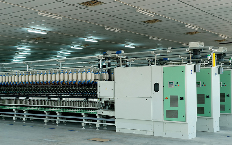
LMW proven spinning geometry enhances the quality and productivity. LMW Ringframes with robust design helps in less maintenance cost, machines with inbuilt Energy saving solution to ensure less Spinning cost and boosts Profitability to Spinners.
Features
- LR9A upto 2016 spindles helps in less space requirement, less humidification comparatively
- Hook Lock Low Decibel (HLLD) spindles with less Vibration & Noise
- In built Energy saver with IE4 main motor, Inverter Controlled IE3 suction motor,Inclined suction tube to improve effective suction
- 4Q-2M drive for drafting
- T-Flex drive system for quality consistency
Flexibility
- Ne range from 8s to 200s can be spun
- Machines with doffer and without doffer option available
- 16 step Speed pattern curve
- Ready to retrofit of Compact/SIRO system
- Spindle pitch 70mm & 75mm option available with lift options from 160 to 240mm
- Pneumatic load and Spring load both the options of Top arm are available
Automation
- Rapid doff system (<100sec doff="" li="" time="">
- Basket Tube loading system for ease of operation
- Yarn Breakage monitoring system & Roving stop motion available as optional
- Machine ready to merge with LMW Spin Connect system with an unique feature called Recipe management
- Power Consumption can be monitored through display
15 comments:
Awesome Blog! Its very interestingly and informative in reading. This is really a great Stuff for sharing. Keep it up. Thanks for sharing.
Box Compression Tester | Testing Instruments
Thank you so much for telling us about Modern ring
RX 7 Advanced Crack
I am very impressed with your post because this post is very beneficial for me and provide a new knowledge to me
Nice information provided by you, it really helped me to understand this topic. I have also referred this article to my friends and they also enjoyed this informative post
download software drivedx-crack
Wow, amazing block structure! How long
Have you written a blog before? Working on a blog seems easy.
The overview of your website is pretty good, not to mention what it does.
In the content!
vstpatch.net
MacX DVD Ripper Pro Crack
PreSonus Studio One Pro Crack
DaVinci Resolve Studio Crack
Garritan CFX Concert Grand Crack
Sound Forge Pro Crack
Fibre Disc are used to grinding curved surfaces of metal. We use this tool prior to painting, polishing, and finishing a product. We use Fibre Disc, after welding or connecting products, we only apply them to dry products. There is a lot of Fibre Disc Manufacturers in India but AbrasiveOnline is the top class Fibre Disc Manufacturers.
Thank you for sharing. This is Very Usefull post. Thanks For Post which have lot of knowledge and informataion thanks.!
Volume Shaper Crack
HDRsoft Photomatix Pro Crack
FastStone Photo Resizer Crack
Movienizer Crack
Coolmuster Android Assistant Crack
Golden Software Voxler Crack
iMyFone LockWiper Crack
Enigma Recovery Professional Crack
PMP CERTIFICATION COURSE
The PMP course provides managers with the latest information on Project Management norms and practices.Click here to know more
pmp certification course
i am very satisfied with your post.it provide a great knowledge to me. Thanks for sharing!. You can also visit my post.
lumionpro
omnisphere
apoweredit
muzepadionekontakt
Such a nice post Keep it up!
izotope vinyl vst
Nice blog, thanks for sharing Vibrating Rod Level Switch
Post a Comment